

Introduction: IR Controlled Stepper Motor Lift


I needed to automate lifting a large picture that hides a TV mounted over a fireplace. The picture is mounted to a custom sliding steel frame that uses ropes, pulleys and counterweights so it can be raised by hand. This sounds good in theory but inconvenient in practice when you just want to watch TV for a few minutes. I wanted to automate lifting the picture with IR commands from a Harmony Hub whenever the TV is turned on.
Step 1:
Here is how the picture was lifted before. As you can see there wasn't enough room to install a typical TV lift. Even if there were enough room, the highest TV lifts advertise they can lift a TV up to 60 inches but that is misleading as their maximum travel is usually only 24 to 30 inches and I needed to move the picture 53 inches. I investigated linear actuators but again there wasn't enough room and I couldn't find a compact one with that much lift. Also there was the problem of figuring out how to actuate it using IR as most use a physical switch or RF remote.
Step 2:
I needed a mechanism that was compact, could travel 53 inches and be controlled by IR. I finally settled on using a large stepper motor with a long lead screw. After an online search I found these two videos. I simply combined the two concepts.
Step 3:
Parts list
High Torque NEMA 23 Stepper Motor https://smile.amazon.com/dp/B00PNEPW4C
NEMA 23 Damper https://smile.amazon.com/gp/product/B07LFG6X8R I was concerned the stepper motor's high frequency vibrations would resonate on the metal frame and make a lot of noise so I used a damper. The stepper was a just a little wider than the angle iron so one side of the stepper would actually be clamped on with screws, nuts and fender washers so I had to use this style damper that has four mounting holes on each end instead of the usual two.
Stepper Motor Driver 1.0-4.2A 20-50VDC https://smile.amazon.com/dp/product/B06Y5VPSFN
Fanless 24V Power Supply https://smile.amazon.com/dp/B074GJ22P6
Arduino https://smile.amazon.com/dp/B008GRTSV6
Micro switch https://smile.amazon.com/dp/B07KLZTHR9 or https://smile.amazon.com/dp/product/B07V6VGV9J depending on how much reach you need. I used a heavy duty switch like this since I was mounting it to angle iron.
IR receiver diode https://smile.amazon.com/dp/B00UO9VO8O These Vishay receivers are supposedly the best.
Clear or smoked Arduino Case https://smile.amazon.com/gp/product/B075SXLNPG Something transparent an IR flasher can penetrate.
Zyltech 8mm T8x8 ACME Lead Screw and Nut ("T8"=8mm diameter; "x8"=8mm lift per revolution) I needed a really long lead screw so I found this 2000mm (78 inches ~ 6.5 ft) one on ebay https://www.ebay.com/itm/323211448286 Luckily this manufacturer includes a heavy duty brass nut with a wide flange. Most other brands have narrow flanges with small mounting holes so close to the shaft that they don't leave clearance for washers and locknuts.
8mm to 10mm Shaft Coupler https://smile.amazon.com/gp/product/B07X4VHYTQ Be sure to use a solid, clamp-style coupler like this as they hold much tighter than a set-screw type and won't damage the shaft or lead screw.
Any IR remote
Wiring between Arduino and Stepper Driver https://smile.amazon.com/dp/B07D58W66X I programmed the Arduino using adjacent pins so I could use a wide header connector like this that won't pull loose easily.
4-conductor wire between Stepper Driver and Stepper https://smile.amazon.com/dp/B07Y34QCDX
2-conductor wire between Arduino and Micro switch https://smile.amazon.com/dp/B07Y332K8T
Euro-style terminal connectors https://smile.amazon.com/dp/B07JNBJYB5
Step 4:
I used the AccelStepper stepper library so I could start and stop the stepper gradually since there was quite a bit of mass involved but I still needed to home the stepper at power up using a Micro switch. I found this YouTube video and tutorial that showed how to home the stepper using regular high/low pin switching before handing off control to AccelStepper for the faster movement.
Step 5:

I used an Arduino Uno and jumper wires for the coding and prototyping phase.
Step 6:
Before I could write the sketch for the lift I needed to find the IR hex codes for the buttons on the remote I was going to use for up and down so I uploaded the attached sketch to Arduino and opened the serial monitor to view the codes while I pressed buttons on the remote.
P.S. This is my first Arduino project on Instructables. For some reason the code gets garbled when I use either the code format option or attaching as plain text so I uploaded it with a .c extension. Just rename it with Arduino's .ino extension. Or .txt if you just want to take a quick look at it.
Attachments

Step 7:
The code for the lift itself.
Attachments
Step 8:


I used an Arduino Uno and individual jumper wires for the prototyping phase but wanted to use a 5-pin header cable to prevent the wires from accidentally getting pulled loose. The only full-sized Arduino board I could find without header pins pre-installed was an Arduino Leonardo from the official Arduino store. The code is the same for both except there is a known conflict between the Leonardo's pin 13 LED and IR receiver so I couldn't get the LED to blink for visual feedback when receiving IR signals like I could with the Uno but that was no biggy. The only other notable differences are that the Leonardo uses a micro USB connector and boots much faster than the Uno. I bent the leads of the IR receiver 90 degrees and soldered it in permanently to face the top of the case where I planned to stick the Harmony Hub's IR flasher.
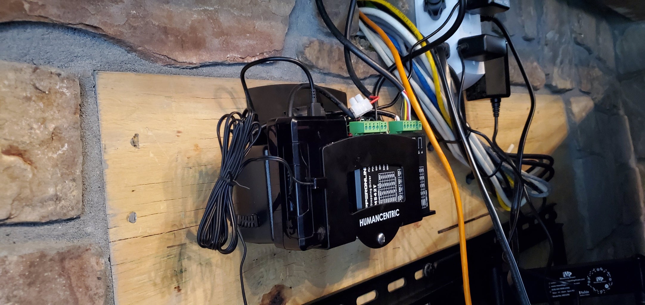
Step 9:


I wanted to keep everything as compact as possible so I found this small adjustable cable box/modem mount https://smile.amazon.com/dp/B077T45BXR to hold the Arduino, stepper driver and power supply. I used velcro and silicone servo tape to keep everything from slipping out when tightening the mount. The step, direction and enable terminals on the stepper driver don't share a common ground and I only had one ground wire coming from the Arduino so I used jumper wires (those little black loops) to connect all the ground terminals together on the stepper driver. That little bare wire sticking out not connected to anything yet is the positive wire for the Micro switch. Basically there's a step, direction, enable, micro switch and ground wire coming from the Arduino.
Step 10:

Installing the ACME nut, lead screw and stepper motor itself was not difficult but I needed a LOT of help removing the picture and counterweights to get to the frame.
Step 11:

ACME nut installed.
Step 12:
Here's a short video of the homing portion of the sketch. It's slow by design as it hunts for the limit switch. Homing starts automatically after every time there is a power loss so the stepper driver knows the stepper's position. If you turn up the volume at the 12 second mark you can hear the micro switch click when it gets pushed in and click again when it gets released after the stepper reverses.
Step 13:
And finally here's the lift in action. It takes 25 seconds to lift the picture 53 inches.
Step 14:

Components mounted behind the TV.
Step 15:

I learned a couple of lessons writing and debugging the code. The first is that the stepper would start homing at power-up even if the Micro switch was disconnected so I instead wired the Arduino to the normally closed (NC) side of the switch and added some code to exit the sketch if the switch is not detected, otherwise, the stepper would never stop homing. If you use the normally open (NO) side of the switch then the Arduino can't tell if the switch is open or simply not attached. The second lesson I learned is that the stepper driver would use power (full or half power depending on a DIP switch setting on the stepper driver) to hold the stepper driver in place when it's not moving. This makes sense for CNC and 3D printing applications but I didn't need it to hold in place for hours at a time (Hint: Half-power holding makes stepper motor not as hot lol) since I was using a relatively neutrally balanced lift mechanism. The solution is to use the stepper driver's ENA (enable) pins. I connected the stepper driver's ENA+ to a pin on the Arduino and the ENA- to the Arduino's ground and simply switched the ENA+ pin to HIGH (On) to tell the stepper driver to shut off power to the stepper between moves. If I were using this to lift a heavy TV I would first try using an anti-backlash nut to see if that was enough to hold it up before using a constantly powered stepper simply to conserve power. I hope this Instructable has been helpful to someone! Thanks for looking!


