Introduction: Making the Ultimate Class-E Musical Tesla Coil (Single-FET SSTC) | a Complete Build Tutorial


Be sure to check out the official tutorial video here: https://www.youtube.com/watch?v=Hez-R-WF5P0
Class-E SSTCs are probably one of the most underrated solid-state Tesla coil types. In the world of "real" SSTCs, they are not only the simplest and cheapest, but also the most efficient (some sources have claimed they can exceed 95% efficiency). Sadly, a lot of the designs out there are old and simply aren't that attractive. The original model by Richie Burnett and plenty of the "classics" that followed (like this one by Eirik Taylor) all use a complex arrangement of inductors and capacitors in the class-E section, with the main drive signal coming from a fixed-frequency crystal oscillator/amplifier setup...yuck! Time for a revamp, wouldn't you say?
Some people have taken the route of antenna feedback and PLL...I didn't want to do that. PLL is still something I'm working up to, and antenna feedback by itself (like in Steve Ward's class-E) didn't work at all for me. So instead, I invented a new kind of class-E driver circuit, based around an adjustable Schmitt trigger oscillator with a range of 100kHz-5MHz! Inspired by Steve Ward's work, the class-E portion of this circuit only has one inductor (the primary coil) and one capacitor, which simplifies things a lot. It doesn't even have an annoying gate drive transformer!
Perhaps the coolest part is the new interrupter that has been specially crafted for this circuit. This new interrupter circuit has probably the widest range of any Tesla coil interrupter: its duty can be varied from 0 - 100%, and the pulse frequency can range from as low as 35Hz up to 35kHz. That's right: this Tesla coil can be interruptedULTRASONICALLY, so the sparks have the silence of a CW flame, but with less power consumption! And with ultrasonic interruption comes the possibility of audio modulation. By feeding an audio signal from a standard 3.5mm headphone jack into the circuit, we can transform our Tesla coil into a miniature plasma speaker, with really crisp audio quality!
So what are you waiting for? Let's get started!
Supplies
For this build, you will need the following parts (all available from Mouser.com, Digikey.com, or similar websites):
- A high-power N-channel MOSFET (500V or greater, over 250W preferably, and at least 15A). The IRFP460 is an excellent option, but I went with the 500W APT37F50B (APT30F50B also served me well). Silicon carbide MOSFETs (SiC) are also excellent options for input voltages past 120V, but they are quite expensive.
- A heatsink that fits your chosen MOSFET (this is a decent option that doesn't require screws). The larger the better!
- One NE555 timer IC (DIP-8 package for the PCB)
- One UCC27524 gate driver IC (again, DIP-8 package for the PCB). May be substituted with similar ICs, such as the UCC27424.
- One 74HC14 Schmitt trigger/hex inverter IC (DIP-14 package for PCB).
- One 7812 12V linear voltage regulator
- One 7805 5V linear voltage regulator
- One bidirectional 1.5KE400CA 400V TVS diode
- One bidirectional 1.5KE18CA 18V TVS diode
- Two standard diodes. I used the 1N5818, but models like the 1N4007 or 1N4148 will work just fine!
- Two bridge rectifiers (at least 500V and 15A recommended). I used the GBU1510.
- Two 4.7 ohm resistors (2W recommended)
- Two 1M potentiometers
- Two 100K resistor (1/4W is fine). The second resistor is used on the PCB to connect the PCB ground plane to mains ground (if the connection is made directly, mains power will destructively short circuit through the PCB to ground unless the power supply is isolated).
- One 1K resistor (1/4W is fine)
- One 620 ohm resistor (1/4W is fine)
- One 200 ohm resistor (1/4W is fine)
- One 10K trimmer potentiometer. In theory, you could swap this for a standard 10K potentiometer, but the PCB was made for the little blue trimmer type.
- One 1K trimmer potentiometer. This is used on the PCB for fine tuning the frequency, and it can be omitted if desired (just short the connections on the PCB if you do omit it).
- One 3.5mm phone connector audio jack
- Two 2.2uF/250V film capacitors. These are to block mains power from entering the audio jack. Recommended lead spacing for the PCB is 5mm to 15mm.
- Two 470uF/50V electrolytic capacitors. 25V capacitors are also perfectly usable, but 50V allows for higher input voltages (the 7812 can handle up to 35VDC, or rectified 24VAC).
- One large 250V electrolytic capacitor (470uF or more is best)
- One 10uF ceramic capacitor (any voltage over 16V is fine)
- One 0.022uF ceramic capacitor (any voltage over 16V is fine)
- One 470pF ceramic capacitor (any voltage over 16V is fine)
- One resonant-size film capacitor (lead spacing of 15mm for the PCB). The voltage should be equal to or greater than that of the MOSFET, and the capacitance depends entirely on the tuning. For my 1.5MHz coil, this 1kV/1500pF polypropylene capacitor would work fine.
Somewhat optional, but highly recommended parts (mainly for the PCB):
- Two DIP-8 sockets (for 555 timer and UCC27524)
- One DIP-14 socket (for 74HC14)
- One 5-position terminal block (for power connections)
- One 2-position terminal block (for the primary coil)
- A smaller heatsink for the 7812
ROUGH TOTAL: $55 (this includes shipping)
Other parts:
- A low voltage transformer or power supply for the circuit's logic section. I recommend either 14VDC - 30VDC or 10VAC - 20VAC. Most supplies will work, since the circuit should pull under 1A.
- A breadboard or the official PCB for this project. Both will cost you roughly $5, so I personally recommend the PCB, since all the connections are already made internally! For the rest of this tutorial, I will be speaking in terms of a PCB-based build.
- A PVC or cardboard tube for the secondary coil to be wound onto (I used a 4.5"-long section of 1.25" PVC pipe, which has an actual outer diameter closer to 1.625"...this is pretty much the same as a toilet paper tube, for all you recyclers out there!)
- Magnet wire for the secondary coil. I used 32AWG wire from Amazon.com
- Coated wire for the primary coil and other interconnections (gauge doesn't really matter, as long as it's thicker than about 20AWG for the primary)
Tools you'll need:
- A soldering iron
- Wire cutters
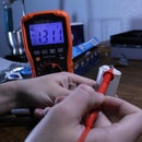
- A multimeter (good for testing/troubleshooting)
- An oscilloscope for tuning (not strictly necessary, but it will save you a lot of trouble and heartbreak)
- A power source of some kind. Unless you're using SiC MOSFETs, this circuit probably won't be able to handle direct 120V. In my case, I used a Variac to supply my circuit with 75V, which seems to be its maximum at such a high frequency. You could also use an LED power supply (a 60V/10A model will cost you about $50 on Amazon), a battery bank, or a transformer of some kind. Current and voltage wise, you'll probably have good luck with 60VAC (or 100VDC) and at least 5A.
Step 1: Order the Parts
WARNING: DO NOT PURCHASE IMPORTANT COMPONENTS LIKE MOSFET’S OR DRIVER IC’S FROM GENERAL SHOPPING WEBSITES LIKE AMAZON OR EBAY! MANY PEOPLE HAVE PURCHASED CIRCUIT COMPONENTS FROM SUCH SITES AND FOUND THEY WERE TOTALLY USELESS. DON’T WASTE YOUR MONEY: BUY SEMICONDUCTORS FROM ESTABLISHED SITES LIKE MOUSER OR DIGIKEY!
Listed above is every part needed to build a your very own class-E SSTC. The links provided go to the associated parts on Mouser.com (one of my preferred sites, next to Digikey.com). While the parts I linked to seem to be decently stocked right now, it is entirely possible that one day, they might go out of stock. If you find a part is out of stock, I encourage you to use your common sense and look for alternatives with similar ratings. Please note, however, that most of these part values are not super critical, and substitutions can be easily made. Additionally, if you possess parts of similar values, feel free to save money and use your own parts instead! Owning a 12VAC transformer of your own could save you an extra $10!
It is also worth noting that having a few extra components on hand isn’t a bad idea. The main components to worry about include the MOSFET, 400V TVS diode, the all of the ICs (74HC14, UCC27524, and NE555), and the high voltage supply’s bridge rectifier. In my experience, the 400V TVS diode is typically the first thing to go, as it essentially sacrifices itself to the high voltage spikes in place of the MOSFET. After the TVS diode goes, the bridge rectifier is typically next in line (since the TVS diode tends to die short-circuited, leading to overcurrent). MOSFETs typically don't die unless you're REALLY pushing your coil or you forgot to replace the TVS diode with a new one. IC deaths are usually the least common, although I have experienced a few. UCC drivers typically die when you crank the frequency above 5MHz (which leads to overheating), and I have had a 74HC14 go bad on me (to be fair, it was used in an experimental context beforehand). ICs are cheap though, so don't be afraid to stock up!
After ordering the main parts, I recommend ordering a set of official LabCoatz PCBs. To order them, simply take the “Electra Mark III” .zip file (downloadable here) and submit it (as a whole, not unzipped) to a PCB manufacturing website like JLCPCB.com. This .zip file is technically referred to as a Gerber file. If you are asked by the PCB manufacturer for the board size, it should be around 84mm by 100mm. If you want, you can change how many PCBs you order and what color they are. The minimum order size with JLCPCB is 5 copies, which costs around $5 with the cheapest shipping for this PCB.
Step 2: The Circuit, How It Works, and Class-E Tuning


Above, you can see the schematic for this Tesla coil. At its core, this design is very similar to Steve Ward's class-E SSTC, but there are a few key changes. For one, the slower UCC37322 has been swapped out for the newer and faster UCC27524, and the old interrupter has been changed out for my own custom circuit, which was derived from the classic musical flyback driver.
Another major change involves how this circuit produces its drive signal. Steve Ward's original circuit utilized an antenna for feedback, much like my previous coils. Sadly, this didn't seem to work in my circuit, so I had to use an oscillator. Most designs use fixed-frequency crystal oscillators, which are both difficult to set up and quite limiting (your secondary coil must be built to match the crystal's frequency almost perfectly). So instead, I went with a very simple (yet surprisingly reliable) adjustable oscillator that, to my knowledge, has never been tried in a Tesla coil before: the Schmitt trigger oscillator!
Here is how it works: an inverting Schmitt trigger (the 74HC14) is set up with a capacitor between its input and ground, and a variable resistor between its output and its input (see the schematic above). When powered up, the input is "low" (0V), so the output goes "high" (5V). Some of the "high" output it directed back to the capacitor at the input through the resistor, and it begins to charge. Once the capacitor is charged to the trigger voltage, the input is perceived to be "high", and the Schmitt trigger sets its output "low". With the output "low", the capacitor bleeds off its energy through the resistor, and the cycle repeats. The on-and-off cycling of the Schmitt trigger's output produces a fairly clean squarewave that is ideal for our driver circuit! Furthermore, the cycling rate is determined by both the capacitance and the resistance, so using a trimmer potentiometer as the resistor allows us to have an oscillator with a tunable frequency!
The rest of the circuit is pretty straightforward: the signal from the Schmitt trigger oscillator goes to the UCC27524 gate driver, which amplifies the signal into a more beefy 12V squarewave. The two outputs of the UCC driver are put in parallel (two separate resistors are used instead of one to protect against internal shoot-through, as recommended by the manufacturer) and the signal is sent to the MOSFET, which switches the main power stored in the large electrolytic capacitor across the primary coil. If the Schmitt trigger oscillator's frequency matches the secondary coil's natural resonant frequency, the oscillating currents in the primary coil will excite the secondary coil with its magnetic field, and we get ourselves a nice high voltage display!
CLASS-E OPERATION
So what makes this a class-E coil and not just another MOSFET slayer exciter? Actually, only one component: a tuning capacitor. The capacitor placed between the MOSFET's drain and source forms a resonant circuit with the primary coil, and if this resonant circuit is tuned just right, the MOSFET will switch on and off when the voltage across it is zero. This is known as zero-voltage switching (ZVS, which also tends to coincide with zero-current switching, or ZCS), and it is the key to keeping the MOSFET stone-cold despite it having hundreds of watts pumped through it. ZVS also helps keep the MOSFET safe from voltage transients. If the FET switches off while current is flowing, voltage transients and ringing will develop that could easily destroy it.
Tuning for class-E operation is actually fairly straightforward, as long as you have a scope. Above, you can see a reference chart that I made showing the main waveforms you're likely to come across (it might be hard to see but, the blue curves indicate the gate signal and the greenish-yellow curves indicate the voltage between drain and source). As you can see, what we are after is a squarewave at the gate that is fully out-of-phase with the sinusoidal waveform at the drain. If the drain voltage hits zero before the MOSFET switches on (indicated by the gate squarewave going high), then the primary circuit is tuned too high, and turns should be added to the primary coil. And if the drain voltage extends into the squarewave, the frequency is too low, and turns should be removed from the primary coil. Pretty straightforward!
Step 3: Build and Operation Tips

SETTING UP AND OPERATING THE CIRCUIT:
- Supply 10VAC - 20VAC (or 14VDC - 30VDC) to the low voltage input (listed as "12V" on the PCB). If you have a scope, measure the signal between the MOSFET gate and source, and ensure the circuit is oscillating.
- Next, apply a low voltage (under 30V) to the main power input (listed as "12-120V" on the PCB).
- Place a fluorescent lightbulb near the coil and start turning the trimmer potentiometers. Stop when the bulb glows the brightest (or, if a discharge is present, stop when it is the longest). The oscillator is now tuned.
- Now, tune the class-E portion of the circuit. If you lack an oscilloscope, this will be particularly difficult to do correctly, but essentially, you just need to adjust the number of turns on the primary coil until the MOSFET experiences minimal heating during operation. If you do have an oscilloscope:
- Connect one probe to the MOSFET gate pin and the other to the drain pin (and the grounds for each probe connect to the MOSFET source pin).
- Adjust the primary coil until the drain voltage is perfectly out-of-phase with the gate voltage. This will ensure the MOSFET turns on when the drain voltage is zero to minimize stress.
- As mentioned earlier, if the drain voltage hits zero before the MOSFET switches on, then the primary circuit is tuned too high, and turns should be added to the primary coil. And if the drain voltage extends into the squarewave, the frequency is too low, and turns should be removed from the primary coil. Again refer to the waveform pictures above if you have trouble understanding!
These setup steps probably won't need to be repeated again, unless the coil falls out of tune for some reason. Once tuned, you can start cranking up the input voltage! If you have a scope, try to monitor the drain and gate waveforms as you increase the voltage. Class-E tuning tends to be somewhat dependent on the input voltage, so what works at 20V might not work so well at 60V. Just something to keep in mind!
The other thing to watch is the peak voltage at the drain. You should stop increasing the input voltage when the drain peak voltages get close 400V (in fact, to be safe, I would recommend staying below 375V at the drain).
And now for a few design tips to ensure you get the most out of your build!
- For one, you want the primary and secondary coupling to be high, but not too high. A coupling coefficient of 0.25 or lower is recommended to avoid throwing off the class-E waveform.
- Next, you want a good balance between resonant capacitor size and primary coil turns. For best results, you should have fewer turns on the primary coil and more tuning capacitance across the MOSFET. A higher capacitance tends to mean less voltage stress on the MOSFET, but keep in mind that primary coils with fewer turns allow higher current flow, which could cause other issues. I personally recommend finding a balance that results in less than 6 amps of current draw during uninterrupted operation, but you are welcome to go higher if you are confident in your tuning and setup.
- One last thing to consider is the MOSFET’s gate capacitance. At super high frequencies, more current is demanded from the gate driver IC to switch the MOSFET on and off, and if the gate capacitance is too high, your UCC27524 will overheat. Just something to keep in mind!
Honestly, given how reliable and easy it is to get this circuit oscillating, there isn't much to say for troubleshooting. There are a few small things though:
- If the circuit shorts out (indicated by lots of current being pulled, and possibly some components "popping"), disconnect the power and feel the MOSFET. If it isn't blisteringly hot, the failure probably resulted from the input voltage being too high. In this case, the TVS diode is the most likely component to have broken.
- If the MOSFET is extremely hot, it probably died from overcurrent or overcoupling and it should be tested. To test a MOSFET, use a multimeter to check the resistance between all of the pins. Normally, there should be near-infinite resistance (or maybe a few megaohms) between all pins, unless you apply a voltage between the gate and source, in which case the drain-to-source connection will have nearly zero resistance (this is how MOSFETs switch "on"). If the MOSFET appears shorted between any of the pins, even after you discharge the gate-to-source voltage, it is most likely dead.
- If there is no perceptible output, try messing with the interrupter potentiometers. If the interrupter duty is too low (i.e. the coil is only "on" for less than 1% of the time), it may appear as though nothing is happening.
- If the circuit is drawing a normal amount of power (usually 5A or less for near-100% duty), but no output is seem (or less output than expected), your oscillator most likely fell out of tune. No worries, some quick adjustment of the trimmer potentiometers should fix the issue!
- If the circuit is not pulling power, you either have a bad connection or your UCC driver isn't supplying a signal to the MOSFET. If the UCC27524 feels hot, it may have burned out and you should try replacing it.
Step 4: FIRE IT UP!!!


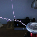
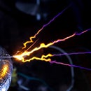
With standard 500V MOSFETs, my coil can handle roughly 75VAC (about 100VDC) before the peak voltages across the MOSFET and TVS diode exceed 400V. Using a 1.5MHz coil and a 3.5 turn primary coil (3.5" in diameter), I was able to produce burning-hot CW arcs over an inch in length, all without any MOSFET heating! However, the real treat comes when you dope the electrode with chemicals: baking soda and table salt both color the arcs a brilliant yellow, lithium compounds produce a deep red or magenta hue, boric acid (sold in stores as a human-safe ant killer) generates a blinding white-green, and potassium nitrate gives a strange mix of orange and purple (and the longest sparks out of all of them)! And if you put a thin piece of steel in contact with the burning-hot CW flame, it ignites into a glorious shower of sparks!
Playing music with this Tesla coil is also super easy: just connect the circuit to the audio player of your choice using a standard 3.5mm headphone cable, crank up the volume, adjust the interrupter to where it is operating at ultrasonic frequencies (the interrupter potentiometers cranked all the way to their minimum resistance), and enjoy the show! I personally used my laptop to play the audio, and I'm happy to say the coil didn't damage it in the slightest. If you want to play it safe though, you might consider picking up an old-school .mp3 player and using that.