Introduction: World's Simplest POWERFUL Solid State Tesla Coil (SSTC)


Be sure to check out my latest Tesla coil build, in which I show exactly how to make your own staccato QCW DRSSTC: https://www.instructables.com/Building-the-Worlds-Easiest-QCW-Tesla-Coil-Staccat/. It's the first tutorial of its kind here on Instructables (and YouTube!), so don't miss out!
Before I begin, I encourage you to check out my how-to video on the LabCoatz YouTube channel, in which I build and demonstrate this incredible circuit: https://www.youtube.com/watch?v=Q0lkg9lxz3s&t. A good friend of mine collaborated with me to help make this video, so give him some love and go check out his video on the subject as well: https://www.youtube.com/watch?v=9b9QqnwCchU&t. Now, let's begin!
Everyone who's anyone want a solid state Tesla coil these days. While spark gap Tesla coils hold the crown as the simplest and most robust Tesla coil variant, they have their issues. Spark gap coils require dangerously high input voltages (over 4kV), noisy spark gaps, and tend to draw a lot of power. Solid state coils (SSTC's), on the other hand, run off low voltages (usually under 400V), produce more energetic sparks, and can be run almost silently. Unfortunately, most SSTCs are quite hard to build. Many require strange driver chips, years of experience, and massive bus capacitors. Well not this one! This coil design can achieve the astounding performance of a traditional SSTC (or even a small vacuum tube Tesla coil) using less than ten circuit components, zero finicky driver IC's, and NO TUNING! Well, what are you waiting for? Let's get started!
Supplies
Please note that all of these components are interchangeable with similar components (I'll talk about each component's requirements later on):
1pcs. N-channel MOSFETwith large heatsink (IRFP460's work pretty well, get two if you want to build an interrupter for the coil)
1pcs. 1k, 1/4W resistor
1pcs. 30k, 1/4W resistor
1pcs. 100nF capacitor (must be rated over 200V)
1pcs. power diode (I used the 10A10)
1pcs. 12V bidirectional TVS diode (I used the 1.5KE12CA)
1pcs. 400V bidirectional TVS diode (I used the 1.5KE400CA)
1pcs. 470pF capacitor (must be rated over 200V)
1pcs. Some form of electrical ballast to limit the current (you can use a hair dryer, toaster, heater element, or even a lightbulb. While testing this circuit, ballast it with a low-power device, like a incandescent lightbulb).
1pcs. A secondary coil (mine was 7" tall and under 2" wide, wrapped with ~35AWG wire, but you can use literally any coil configuration)
1pcs. A primary coil (mine had a radius 1/2" wider than the secondary coil, and had about 3-4 turns of 16AWG insulated wire [no inter-winding spacing]. It was positioned almost half way up the secondary coil)
A soldering iron (kinda optional, but REALLY useful)
Step 1: Pick and Buy the Parts


This coil will be powered with the 120VAC from an ordinary home wall socket. The reason for this is twofold. First of all, basically EVERYONE (in the USA) has an electrical outlet available to them, as opposed to something like a 30VDC supply, which many DIY SSTC's sadly seem to require. Second, 120V is the highest voltage that ordinary people have access to, so logically it has the greatest potential for generating massive SSTC sparks! Since this coil will be utilizing 120V, all parts must be able to handle these conditions and MORE. If you are trying to build this circuit in a 220-240V region, I suggest trying this circuit: https://www.youtube.com/watch?v=MG-pD43i_6A. It is basically the exact same as my circuit, but is modified to handle 240V-operation.
SSTC's are very extreme circuits, so the components must be capable of dealing with some abuse without dying. You can get basically everything you need to build this coil from Digikey.com or Mouser.com. Their components are fairly priced and from my experience, they'll get to you in under a week using the cheapest shipping option ($5-7 USPS). You don't even need to make an account with them to get top-of-the-line parts! In total, this coil can be built for under $50 (and less than $25, if you already have some of the parts handy), making it the perfect entry-level SSTC.
Let's start with the heart of the circuit: the N-channel MOSFET. You can use almost any MOSFET, as long as it's rated for over 300V, can handle continuous currents over 5A and peak currents over 20A, and can dissipate over 250W of power. I used the IRFP460 in my circuit, with which I was able to get sparks up to 5" with a 7" secondary coil (and 8" sparks from a 14" coil).
In order for the MOSFET to handle these high power levels, it must be connected to a fairly large heatsink. Air flow is recommended to keep the MOSFET cool and running at peak performance. A water cooled heatsink would theoretically work the best, but that's getting a little advanced for our simple circuit.
Next up, we have our capacitor. This cannot be an electrolytic capacitor, since they will just explode from the high switching rates. I found film capacitors to be the best option for this circuit, but ceramic type capacitors may also work well. Most schematics suggest using a 1uF capacitor in this circuit, but I found that I got far better performance from smaller capacitors. My coil currently uses a 0.1uF (100nF), 250V film capacitor, which I found produces arcs over 25% larger than this same circuit using a 1uF capacitor. The voltage rating of any capacitor in this SSTC must be over 200V (over 400V if you're attempting to build this coil in a country that utilizes 220VAC).
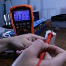
Now for the resistor array. You'll need two resistors which, in my case, were a 2.2k and 45k resistor (both rated for 1/4W, but I later found a 1k and 30k resistor works better). A potentiometer can be used in place of these two resistors, but they seem to be somewhat more finicky and prone to degradation.You can use almost any arrangement of resistors in this SSTC, but the following must be true: if you take the resistance of the smaller resistor and divide it by the combined resistance of the two resistors, the value should be between 0.03 and 0.05. WHY??? Because this will ensure a voltage between 4-6V reaches the MOSFET gate, which is necessary to make the circuit resonant. I'll explain the circuit in more detail later. The smaller the value (say, closer to 0.03), the lower the SSTC's power consumption should be. Also make sure the resistance of this array (or potentiometer) does not exceed 50,000 ohms total! From my experiments, using resistors larger than this will cause the MOSFET to die even when ran at low power levels.
The 12V TVS diode can be almost any bidirectional 12V TVS diode OR a set of two 12V fast zener diodes wired in opposing directions (cathode-to-cathode or anode-to-anode). Higher power diodes are preferred for their robustness, but lower power diodes will also work (since, in theory, they will only be conducting the occasional voltage peak). My personal preference is the 1.5KE12CA, which is rated with a total overkill power rating of 1.5kW with 200A peaks. Some people have gotten away with using a 15V or even 18V TVS diode, but this is not recommended. Strictly speaking, this TVS diode is not necessary for the coil to perform. It is only present to protect the MOSFET's gate from overvoltage. The circuit will work fine without it, but the MOSFET will likely die sooner.
It is also a good idea to put another, higher voltage TVS diode across the MOSFET's drain-to-source connection. I ended up using the 1.5KE400CA, which has proven quite effective at saving my MOSFETs from voltage spikes! Again, this extra TVS diode isn't necessary for the coil to work, but it just might save you a couple MOSFETs like it did for me!
The capacitor at the secondary coil's base should be mains voltage rated (or higher) and very low capacitance. In my circuit, I used a 2kV 470pF film capacitor, since I had some on hand. For safety reasons, I recommend the capacitance be below 5nF, otherwise enough low frequency AC may be passed to cause a noticeable shock (non-harmful, if the capacitor is still small, but potentially undesirable).
Since the circuit runs off of DC, a ballast and rectifier diode are placed in series with it and the 120VAC mains powering it. The power diode should be able to handle 5 to 10 amps at a few hundred volts (any voltage over 250V should be good). I picked the 1kV, 10 amp 10A10 diode, which has a remarkably low price. The ballast can be almost anything you have lying around that plugs into a wall socket. The ballast serves to limit the current entering the coil, since plugging the SSTC straight into a wall socket would just fry it. I found a 5-10A ballast provides decent results without overheating the MOSFET too much. I have tried using a microwave transformer as a ballast, but this inevitably leads to the MOSFET dying (since peak currents can easily exceed 100A in a DC circuit). While your coil is in the testing/optimizing phase, it's best to use a low-power ballast so you don't fry your MOSFET if you accidentally misconnect something. I personally recommend a incandescent lightbulb for this purpose.
Finally, we have the two coils. Both the primary and the secondary can be any size you want, but there are a few things you should know. First the circuit's performance increases the closer the primary coil is to the secondary coil's center. Second, the number of turns on the primary coil determines both the power intake and the arc size. The smaller the primary coil, the more power the circuit consumes, and the larger the arcs will get. I found 3 to 4 turns on the primary coil works best with most secondary coils, and yields a decent arc size for the amount of power consumed. Third and finally, it's best to use insulated wire on the primary coil to help discourage coil-to-coil arcing.
If you want bigger sparks, you might consider adding a topload to the secondary coil. You can use basically anything metallic for this purpose, such as a metal pie tin, a foil-covered tennis ball, or, in my case, a ~7" foam-core toroid for this. Using a topload can both lower the circuit's power intake and even DOUBLE the length of the sparks (it can also shrink the output if too large, so be sure to experiment!). The topload should have something pointy on it (usually called a breakout point) to help the sparks initiate.
Step 2: Build the Circuit

If one wishes to design a solid state Tesla coil, they must understand the circuit itself. Don’t worry, it’s not too complicated, I PROMISE. I've looked at schematics from all over the Internet, and pieced together my own schematic that I feel it much easier to understand (mostly because it is in English, not Russian). To start, the circuit is powered by the 120 volts from an ordinary wall socket, which is rectified into direct current by the single power diode and current-limited by the ballast. The current then passes by a small capacitor, which, contrary to popular belief, is not actually a resonant capacitor (as far as I know!). Its main job is to help smooth the DC waveform slightly and provide higher peak currents during operation. While this doesn’t sound like much, I have tested the circuit without the capacitor and it did not work, so the capacitor is definitely necessary. At the heart of our circuit is a high-power, N-channel MOSFET. A MOSFET is basically a voltage-dependent switch with three pins: a gate, a drain, and a source. Electricity is allowed to flow from the drain to source if a sufficient voltage is applied between its gate and source. MOSFETs will break if the gate-to-source voltage is too high though, so a bidirectional 12V TVS diode is connected to the gate and source to stop voltages over 12 volts from accumulating. A 400V TVS diode is also added across the drain and source to neutralize voltage spikes from the primary coil switching. The circuit will work without these TVS diodes, but the MOSFET is likely to die much faster. The gate of the MOSFET is additionally connected to the bottom of the secondary coil and the middle terminal of a two-resistor voltage divider or potentiometer. Between the secondary coil base and the FET gate is a small capacitor, to stop low frequency mains voltage from travelling back up the secondary coil and shocking unaware individuals. Finally, the primary coil is connected in series with the MOSFET, typically on the drain side.
During operation, the potentiometer or resistor array acts as a voltage divider, supplying around 5 to 10 volts to the MOSFET gate. This turns the MOSFET on, allowing current to flow through the primary coil. The primary coil then develops a magnetic field around it that induces a voltage in the secondary coil. The voltage at the secondary coil’s base opposes the voltage at the MOSFET gate, thus turning the MOSFET off. Once the secondary pulse ends, the MOSFET is turned back on by the voltage divider, and the cycle repeats. This on-off cycling occurs at the natural resonant frequency of the secondary coil, which in turn drives the circuit to produce incredibly high voltages at the secondary coil. This high voltage buildup results in the beautiful, fractal ionization of air that we all know as an electrical discharge.
Step 3: FIRE IT UP!!!


As soon as this circuit is connected to power, it should start electrically oscillating. A good test to see if your SSTC is oscillating is to hold a fluorescent, neon, or CFL type lightbulb near it. If the coil is operating, the bulb should light up. If the coil does not work, try changing the connections on the primary coil or making the secondary coil's base connection more secure. This tends to fix the problem the majority of time.
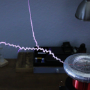
At only 20W input, this circuit produces a faint purple discharge if it has no topload and a very fine tip. As the power increases to 120W input (using a 5A ballast, with the coil self-limiting its current to around 1A), the sparks grow to over 1" long. At the highest power levels the IRFP460 can deal with (using a 10A ballast, self-limited to around 1.7A), the arcs grow an additional inch or so...and then you put on the topload. With a toploaded secondary and breakout point, this coil can easily generate beautiful, 5" sword sparks. Throw some chemicals on the breakout point, and you've got yourself a show-stopping color display (those orange sparks in the above picture are from ordinary TABLE SALT)! You can even touch the ~100kV arcs from secondary safely without feeling ANYTHING! However, touching the sparks will cause the circuit to draw more power, and if contacted for too long at a high enough power level, the MOSFET will burn out. In another project, I show how to build a better SSTC with an interrupter that allows it to be run indefinitely at the highest power levels possible: https://www.youtube.com/watch?v=zCf-PwXsG_E
Anyways, that's all for now. Until next time, my friends! LabCoatz, out!