Introduction: 10 Basic Arduino Projects
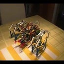


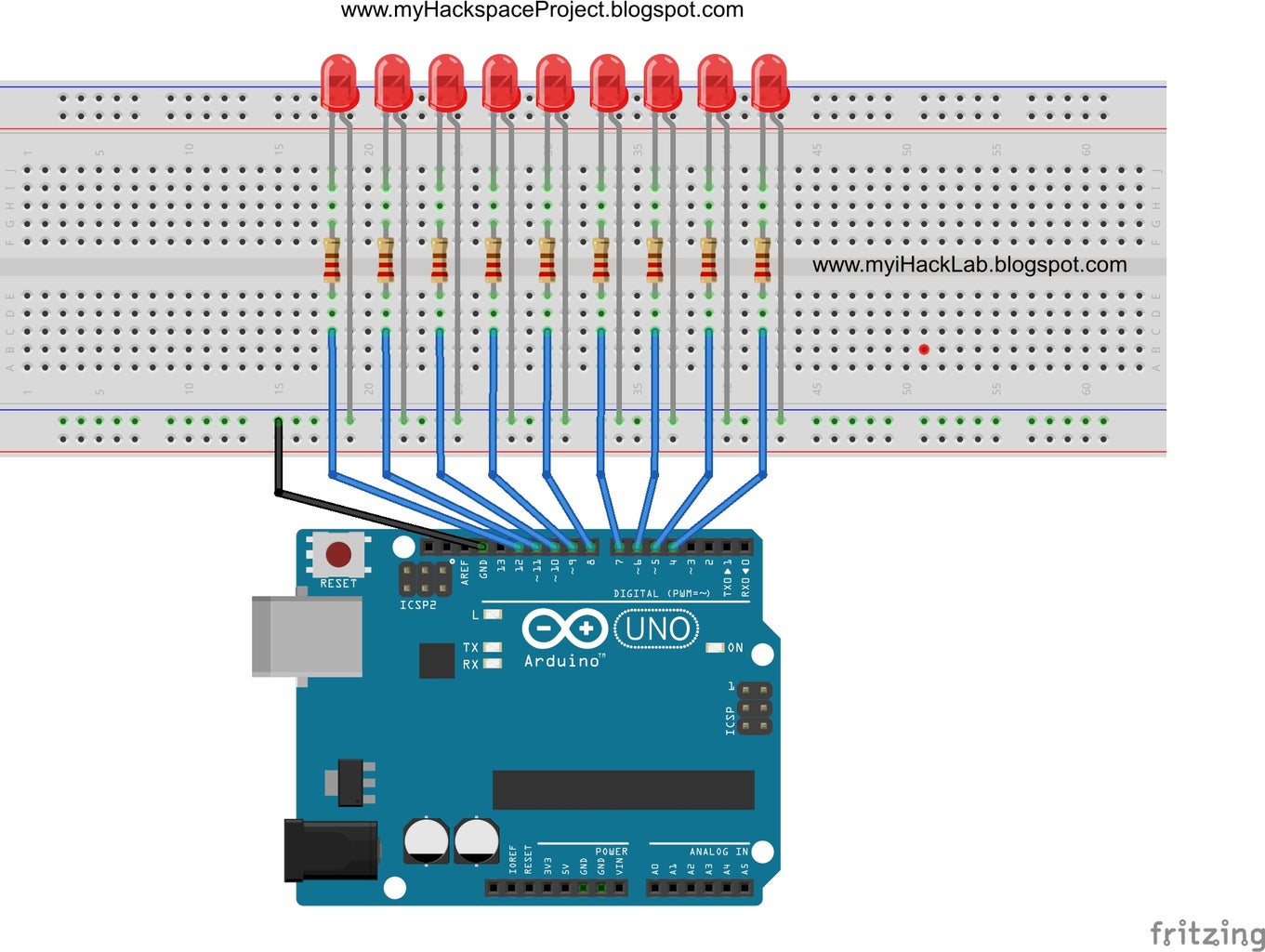
The prototype in the video is used through out your first 10 basic Arduino projects. The actual layout has no messy soldering and complex programming. From this setup, you will actually learn more than 20 projects, if and only if you will do all the interesting challenges provided in each tutorial. This prototype is your stepping stone to the world of robotics and automation.
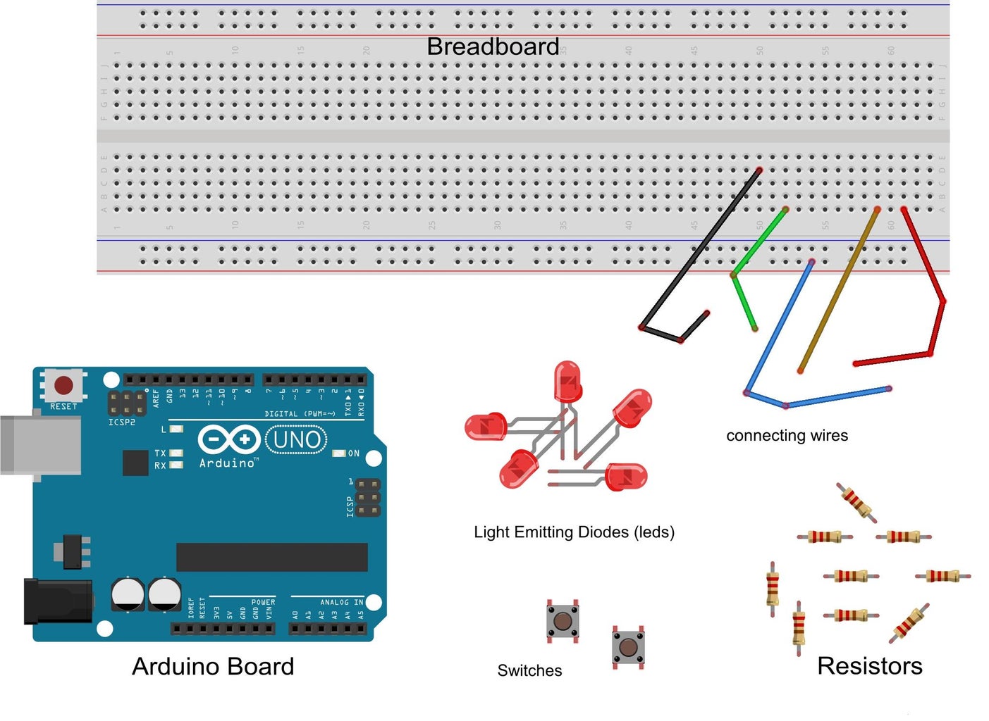
Your First 4 Components:
As a starter, you will only use 4 basic materials:
- LEDs, 9 pcs
- Resistors, 9 pcs, 200 ohms
- connecting wires
- Arduino UNO
Your First 10 Arduino Projects:
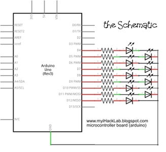
With all these 4 components, you will be making the following 10 arduino projects. The schematics, block diagrams, and actual layout are all posted in the STEP 1 section below.
- 1. The Blinking Red
- 2. Let There Be Lights:
- 3. The Blinker: Blinking Lights
- 4. The Jumper : Jumping Lights
- 5. The Breaker: Dividing Lights
- 6. The Roller: Rolling Lights
- 7. The Knight Rider: Chasing Lights
- 8. Binary Counter: Counting Lights
- 9. The Tester: Testing Lights
- 10. Game of Logic: Thinking Lights
Aside from the above arduino projects, you will also learn how to control a robot, appliances, cars (toys and real) remotely through the internet, your own website, via a wifi, an ethernet, a TV remote control, your computer monitor, your keyboard, your mouse, bluetooth, an iphone, an ipad, your watch, and even with your voice.
Your First Sketch:
/*Project Chasing Lights (Knight Rider Version)
  powered by Arduino
  sketched by J.B. Wylzan
Turns on LEDs from left to right then right to left continuously.
  This example code is public domain.
 */
// Setup pins 4 to 12
void setup()
 {
  pinMode(4, OUTPUT);
  pinMode(5, OUTPUT);
  pinMode(6, OUTPUT);
  pinMode(7, OUTPUT);
  pinMode(8, OUTPUT);
  pinMode(9, OUTPUT);
  pinMode(10, OUTPUT);
  pinMode(11, OUTPUT);
  pinMode(12, OUTPUT);
 }
// Turns LEDs On and Off from left to right repeatedly,
void loop()
{
  digitalWrite(4, HIGH);   // turn the LED on
  delay(100);
  digitalWrite(4, LOW);    // turn the LED off

  digitalWrite(5, HIGH);   // turn the LED on
   delay(100);
  digitalWrite(5, LOW);    // turn the LED off
  digitalWrite(6, HIGH);   // turn the LED on
  delay(100);
  digitalWrite(6, LOW);    // turn the LED off

  digitalWrite(7, HIGH);   // turn the LED on
   delay(100);
  digitalWrite(7, LOW);    // turn the LED off
  digitalWrite(8, HIGH);   // turn the LED on
  delay(100);
  digitalWrite(8, LOW);    // turn the LED off

  digitalWrite(9, HIGH);   // turn the LED on
  delay(100);
  digitalWrite(9, LOW);    // turn the LED off

  digitalWrite(10, HIGH);   // turn the LED on
  delay(100);
  digitalWrite(10, LOW);    // turn the LED off

  digitalWrite(11, HIGH);   // turn the LED on
  delay(100);
  digitalWrite(11, LOW);    // turn the LED off

  digitalWrite(12, HIGH);   // turn the LED on
  delay(100);
  digitalWrite(12, LOW);    // turn the LED off

   digitalWrite(11, HIGH);   // turn the LED on
  delay(100);
  digitalWrite(11, LOW);    // turn the LED off

  digitalWrite(10, HIGH);   // turn the LED on
  delay(100);
  digitalWrite(10, LOW);    // turn the LED off

  digitalWrite(9, HIGH);   // turn the LED on
  delay(100);
  digitalWrite(9, LOW);    // turn the LED off

  digitalWrite(8, HIGH);   // turn the LED on
  delay(100);
  digitalWrite(8, LOW);    // turn the LED off

  digitalWrite(7, HIGH);   // turn the LED on
  delay(100);
  digitalWrite(7, LOW);    // turn the LED off

  digitalWrite(6, HIGH);   // turn the LED on
  delay(100);
  digitalWrite(6, LOW);    // turn the LED off

  digitalWrite(5, HIGH);   // turn the LED on
   delay(100);
  digitalWrite(5, LOW);    // turn the LED off

}


//end of the sketch
Your Knight Rider Procedure:
- Use the prototype above
- Open the Arduino Interface
- Select File > New
- Copy your first sketch
- Paste the sketch on the editor
- Click File > Save
- Click Verify
- Click Upload
- All 9 leds must turn On and Off from left to right and right to left continously
Your Challenges:
- Turn on and off one led
- Blink one led
- Blink all even leds
- Blink all odd leds
- Turn on/off 5 leds to the left and 5 leds to the right chasing non-stop
- Turn on/off all leds chasing in circular motion continously
- Switch leds to count in binary
- Build a traffic or railroad warning lights
- Make a continuity or led tester
- Develop a guessing game
With the iHackRobot Lab Team impression of the classical "Hello World", we welcome you by saying: " Let there be Lights "
Disclaimer: We shall not be liable for any loss or damage of whatever nature - direct, indirect, consequential, or otherwise - which may arise as a result of your use of any information on this website. However, if you are interested in using any of the projects for personal or educational purposes, please inform the author by email.
"The Last Human on Earth will no longer be Human." ~ Joey Lawsin
====================================================
The Homotronics® and Homodruinos® logos are registered trademarks.
Copyright Biotronics© Inc. iHackRobot®.
All Rights Reserved. Patent Pending. 2000 © ® ====================================================
Step 1: Schematics/block Diagrams and Actual Project