

Introduction: AI Self Driving Car


Self-driving cars, also known as autonomous vehicles, are a revolutionary innovation in the automotive industry that is transforming the way we conceive transportation. These vehicles are capable of moving safely and efficiently on roads and urban environments without direct human intervention. They use a combination of sensors, cameras, radars, and advanced navigation systems to perceive their surroundings, interpret signals, and make real-time decisions.
The development of self-driving cars has been driven by leading technology companies and automakers, who have invested significantly in research and development to bring this vision to reality. As technology has advanced, autonomous cars have evolved from mere prototypes to become an increasingly common presence on our roads.
The potential benefits of self-driving cars are vast, ranging from reducing traffic accidents to optimizing traffic flow and improving accessibility for people with mobility impairments. However, they also pose regulatory, ethical, and safety challenges that must be addressed before widespread adoption. Despite these challenges, the future of mobility seems inevitably linked to the proliferation of self-driving cars, promising a radical shift in how we get around.
Creating a scale model of a self-driving car is more than just an engineering exercise; it's an opportunity to explore the future of mobility and inspire innovation. These miniature models allow you to visualize and better understand the operation of autonomous vehicles, as well as their numerous advantages.
By building a scale model of a self-driving car, you're participating in the realization of a revolutionary vision that is transforming the automotive industry. Furthermore, you immerse yourself in a creative process that challenges your technical skills and fosters your creativity.
Creating a scale model also gives you the opportunity to experiment with different designs and technologies, exploring new ideas and innovative solutions to the challenges facing autonomous driving.
Moreover, by exhibiting your scale model, you can inspire others and generate interest in self-driving car technology, thus contributing to the advancement and dissemination of this exciting innovation.
In summary, making a scale model of a self-driving car is not only an exciting and educational project, but it also puts you at the forefront of the technological revolution that is transforming how we get around. Let your imagination soar and bring the future of mobility to life in your hands!
Join me on this incredible adventure of creating a scale model of a self-guided car.
Supplies
See supplies in steps below
Step 1: Description and Scope of the Project
The project is divided into three main parts
- Car: Mechanical Components
- Car: Electronic Components
- Treadmill
Let's see the characteristics of each part:
Part One: Mechanical Components
A low-cost 1/10 scale remote control model kit was selected that would allow the option of making improvements. After analyzing various models, the HSP 94123 kit was chosen, since it is the basis for assembling a scale Nissan GTR model. For the power transmission system, a 550 type brush motor and its speed controller card (ESC) were chosen.
Part Two: Electronic Components
The car has two types of cameras: a 1.2 Megapixel camera equipped with a 160-degree lens and a stereoscopic camera with two 75-degree lenses.
The cameras are connected to a Raspberry Pi 4 equipped with a Google Coral USB, which is a unit capable of processing 4 trillion operations (tera-operations) per second (TOPS). To manage the distance sensors, rear lights, steering servo and speed control card, as well as the processing of Radio control signals, a Wemos D1 R32 board is used, which is an ESP32 mounted on a PCB of the Same format as an Arduino UNO, this allows us to mount shields to test various electronic components.
Part Three: Treadmill
I designed a treadmill for this car to allow control and navigation testing without having to go behind the car on a test track, this way you can interact with the car at your desk.
The front of the treadmill is designed to handle the incline angles that the Ackerman steering has.
IMPORTANT: This is a project in development and the scope of this INSTRUCTABLE includes only the hardware part (Chassis & Electronic Components). However, at the end, in the software section, some guidelines are given on the path that is being followed to test this concept.
This is the first version of the Hardware and during its implementation, construction details have been found that will be corrected in the next version. Likewise, at the end, the modifications that are being taken into account for the next version are announced.
Every effort has been made to ensure that this first version is as close to the desired design as possible.
The purpose of this INSTRUCTABLE is to give you the bases so that you can create your own self driving car from a solid base.
As soon as a new version is available, this INSTRUCTABLE will be updated.
Step 2: DESIGN BASIS

The construction of the car must be carried out on a chassis of a low-cost 1/10 scale model that can be easily acquired.
The motor must be a brushless motor and model 550.
The car must be able to be handled in two ways: a manual one through a radio control transmitter and an automatic one, where the car is guided by means of a computer.
The car must be equipped with vision cameras. A wide-angle lens to allow a panoramic view of the environment and make vision algorithms for object recognition easier and more efficient. The other camera must be stereoscopic so that the distance at which objects are in front of the camera can be determined. As an auxiliary system in distance detection, the car must have the option of using an optical distance sensor. The cameras must be placed in the front of the car in the grill area.
The car must have at least rear stop and turn lights.
The computer inside the vehicle must be a Raspberry Pi 4 or higher. To process the images from the cameras and detect objects and determine trajectories using AI tools, the car must be equipped with a Google Coral USB drive that allows processing up to 4 TOPs. To manage the radio control signals, the management of the motor speed regulator card, the steering servo and the distance sensors, a Wemos D1 R32 card should be used, which is an ESP32 microcontroller mounted on a board with the format of an Arduino UNO, in this way the features of the car can be expanded by placing shields on the top. The Wemos R32 card is managed by the Raspberry Pi through a USB port (serial connection), which at the same time provides it with power.
The electrical system should be composed of 18650 type Lipo batteries, separating the batteries into two groups: one to drive the electronics and the other to power the motor.
The signals between the Raspberry Pi and the Wemos D1 R32 are via serial port and using parser algorithms to send commands between them.
Step 3: Design Recommendations - BEFORE STARTING 3D PRINTING

Efficient 3D Design: Use 3D design software like SolidWorks, Fusion 360, Tinkercad, or Blender to create your model. Ensure you are familiar with the chosen tool.
Design the structure to require the least amount of supports during printing. This will make printing easier and reduce the time and material needed.
Print Orientation: Plan the orientation of the part on the 3D printer to minimize the need for supports. Often, a flat orientation is the best choice.
Avoid sharp angles or excessively long overhangs as they might require supports or be prone to deformation.
Printing Material: Choose a suitable material for your application. PLA is common for prototypes, but if you need more strength, consider ABS, PETG, or Nylon. For specialized applications, you might consider materials like TPU for flexibility or resin for high resolution.
Wall Thickness and Infill: Adjust the wall thickness and infill of your design according to your needs. Parts that need to be stronger can have thicker walls and more infill, while less critical parts can be lighter.
Easy Assembly: Design parts that are easy to assemble without the need for additional tools. Consider using clips, bolts and nuts, or slot and tab systems to keep parts together.
Consider Tolerances: Take into account tolerances to ensure that the printed parts fit together properly. 3D printers can have some variability in the dimensions of printed parts.
Modular Structure: Divide the structure into smaller modules that can be printed separately and then assembled. This makes printing, troubleshooting, and part replacement easier.
Iterative Testing: Prototype and test with 3D-printed parts before printing the complete structure. This allows you to make adjustments and improvements to the design without wasting time and material.
Documentation: Document your design in detail. Provide clear assembly instructions, a parts list, and any additional information that might be useful for others looking to build the same robot.
Consider Functionality: Ensure that the structure can accommodate all necessary components, such as motors, wheels, sensors, and circuit boards.
Strategic Reinforcements: If needed, you can add reinforcements in critical areas of the structure to increase strength and durability.
Optimize for Weight: If mobility is a significant factor, look for ways to optimize the weight of the structure without compromising strength.
Respect Copyrights: If you are using pre-existing designs or third-party components, make sure to respect copyrights and relevant licenses.
Step 4: 3D PRINTING: Grille-Front Bumper, Cameras Support & Sensor Support


The following files contain the parts that we need to print that are part of the GRILLE & CAMERAS SUPPORT:


Step 5: 3D PRINTING: Battery Holder
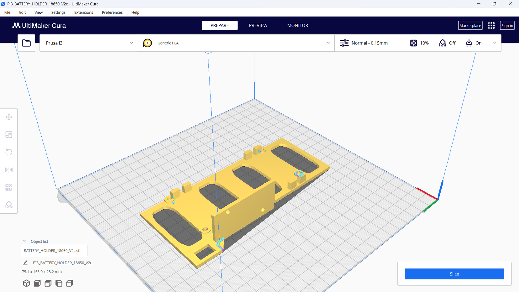


The following file contain the part that we need to print that are part of the ENERGY SYSTEM:

Step 6: 3D PRINTING: Electronic Components Base


The following files contain the parts that we need to print that are part of the Components Base:
Attachments

Step 7: 3D PRINTING: Rear Lights


The following files contain the parts that we need to print that are part of the Rear Lights:
IMPORTANT: To print the right light, in the 3D printer software clone the left part and apply the mirror effect, in this way the right part of the rear light will be created.


Step 8: 3D PRINTING: Car Treadmill


The following files contain the parts that we need to print that are part of the TREADMILL:
IMPORTANT: The PLUG part must be cloned 15 times
Attachments


Step 9: 3D PRINTING: Post Processing

Once the 3D printer has finished its work, it is often necessary to work on the part itself: this is where post-processing comes in. Post-processing includes several steps on the cleaning of the parts. The goal is to remove all excess material.
The post processing steps are:
- Support Removal
- Sanding
- Joining
- Priming & Painting
Tools that we are going to use in this step:
- Dremel
- Dremel 432 Sanding Band
- Dremel 932 Aluminum Oxide Grinding Stone
- Dremel 9901 Tungsten Carbide Carving Bit
- Retracting-Blade Utility Knives
- Straight Rectangular File for Coarse Finish, 8" Long x 1/2" Wide
- Sanding Sheet with Paper Abrasive Backing, for Smooth Finish, 220 Grit
- Drill Bits: 1/8", 5/32", 13/64", 7/32", 4mm, 8mm
- HSS Straight Groove Step Drill Bit 3-12mm
Step 10: POST PROCESSING


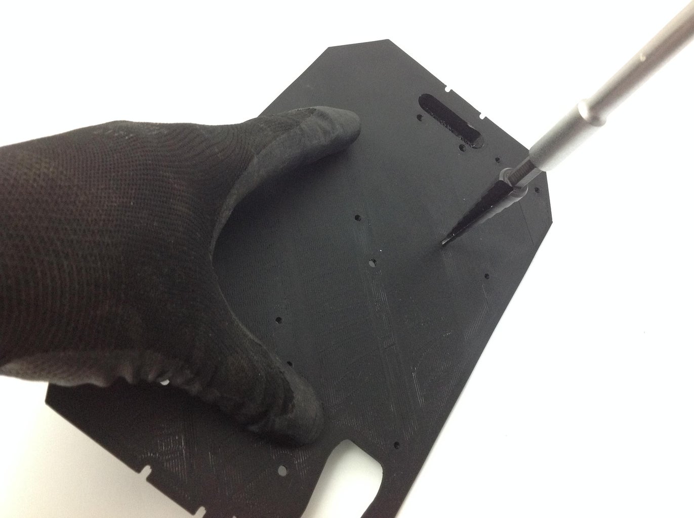
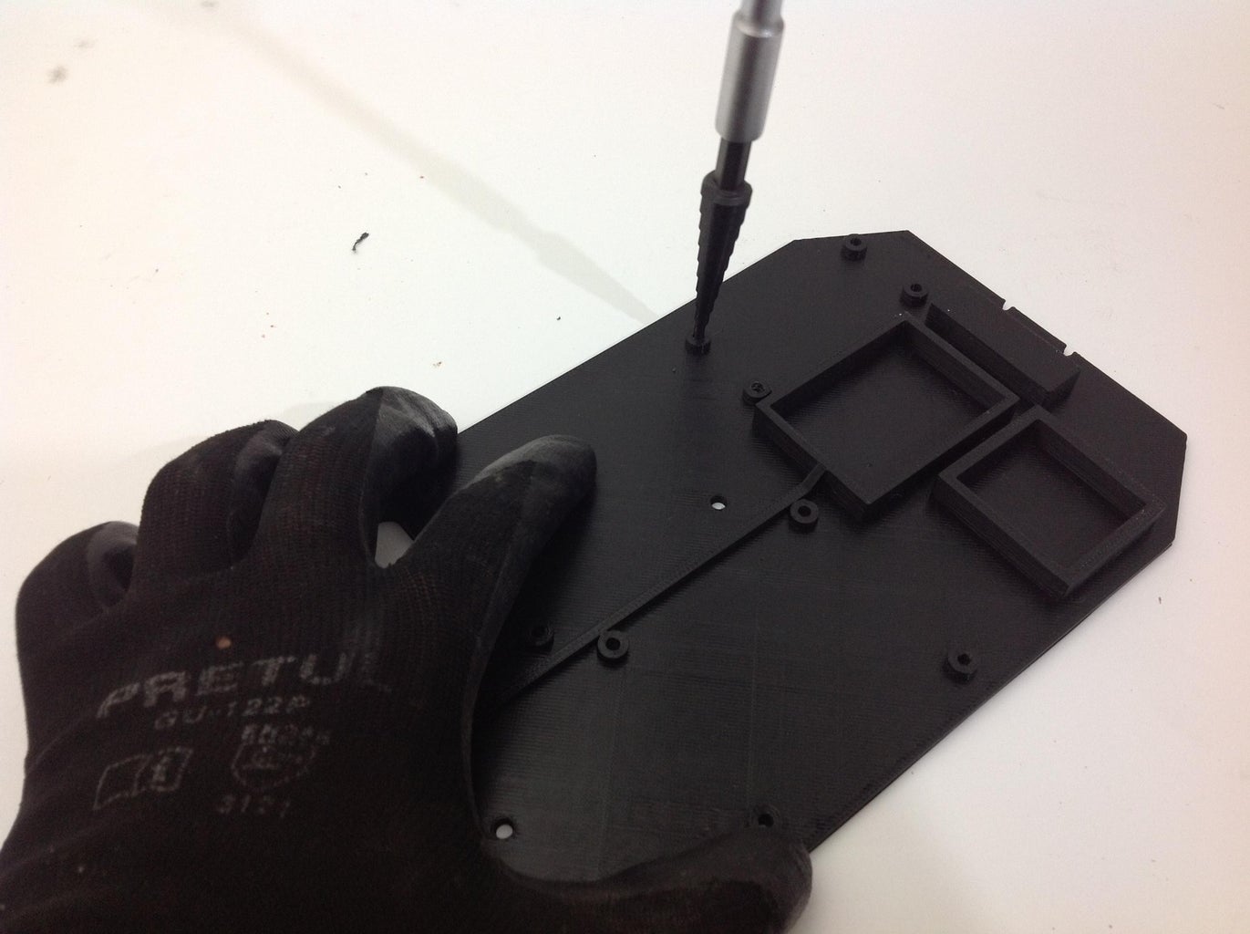
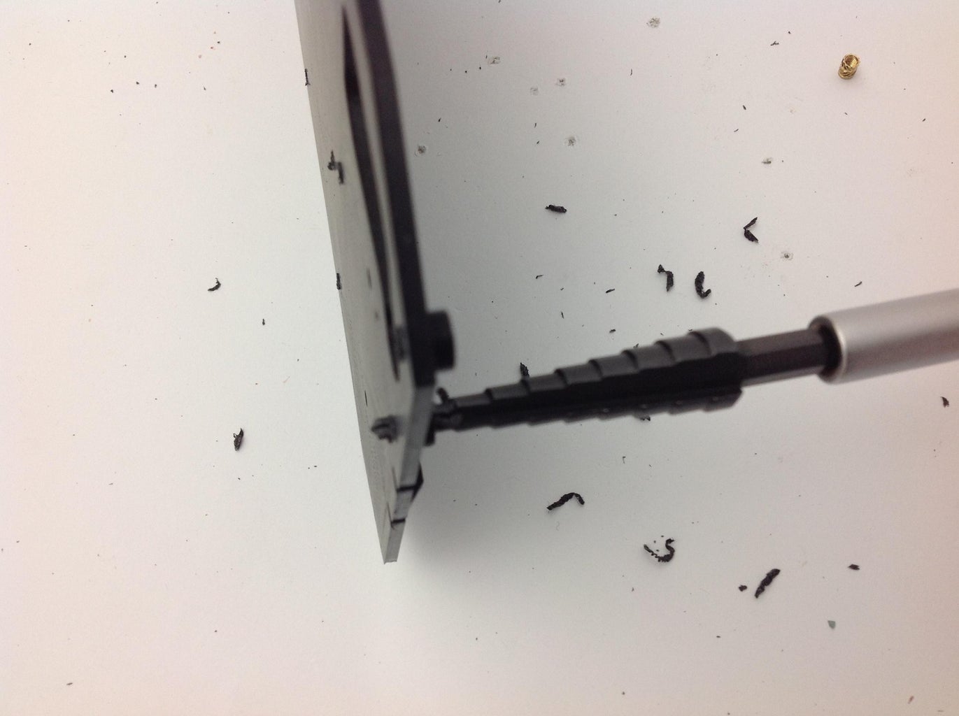

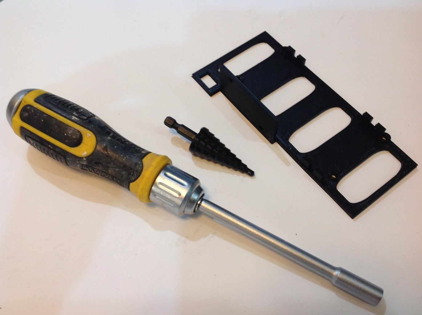

Use a Straight Rectangular File for Coarse Finish, 8" Long x 1/2" Wide to remove excess plastic.
Use a HSS Straight Groove Step Drill Bit 3-12mm to drill the holes for the M3 screws to go through.
Step 11: HEAT SET INSERTS


For Heat-set inserts tutorial, follow this link
TOOLS:
Heat Insertion Tool For Plastic 3D Printer Soldering Iron
MATERIAL:
Heat-Set Inserts for Plastic, Brass, M3 x 4.2 mm, 3 mm Installed Length x 2 (for Step Down Converter)
Heat-Set Inserts for Plastic, Brass, M3 x 4.2 mm, 3 mm Installed Length x 2 (for Laser Sensor Support)
Heat-Set Inserts for Plastic, Brass, M3 x 4.5 mm, 4 mm Installed Length x 3 (for Cameras_Nuts.stl)
Heat-Set Inserts for Plastic, Brass, M3 x 4.5 mm, 4 mm Installed Length x 2 (for Grille)
Heat-Set Inserts for Plastic, Brass, M3 x 4.5 mm, 4 mm Installed Length x 6 (for Rear Lights support)
Heat-Set Inserts for Plastic, Brass, M3 x 4.5 mm, 4 mm Installed Length x 4 (for Battery Holder)
Heat-Set Inserts for Plastic, Brass, M3 x 4.5 mm, 5 mm Installed Length x 8 (for Electronics Support Base)
STEPS:
Carefully using the insertion tool, install the insertion nuts as shown in the pictures.
Step 12: PLACING HEXAGONAL SPACERS


TOOLS:
Hobbypark RC Car Wheels Tools Metal Hex Hexagon Sleeve Wrench Cross Wrenches (4mm, 5mm, 5. 5mm, 7mm)
MATERIAL:
M3 Male Female Hex Spacer Standoff Screw Nut Threaded Pillar (M3 6mm + 6mm) x8
M3 Male Female Hex Spacer Standoff Screw Nut Threaded Pillar (M3 12mm + 6mm) x4
STEPS:
Install the M3 Male Female Hex Spacers Standoff Screw as shown in the pictures.
Step 13: DESCRIPTION of COMPONENTS
Step 14: COMPONENT DESCRIPTION: Raspberry Pi 4

Specifications
- Broadcom BCM2711, Quad core Cortex-A72 (ARM v8) 64-bit SoC @ 1.8GHz
- 1GB, 2GB, 4GB or 8GB LPDDR4-3200 SDRAM (depending on model)
- 2.4 GHz and 5.0 GHz IEEE 802.11ac wireless, Bluetooth 5.0, BLE
- Gigabit Ethernet
- 2 USB 3.0 ports; 2 USB 2.0 ports.
- Raspberry Pi standard 40 pin GPIO header (fully backwards compatible with previous boards)
- 2 × micro-HDMI® ports (up to 4kp60 supported)
- 2-lane MIPI DSI display port
- 2-lane MIPI CSI camera port
- 4-pole stereo audio and composite video port
- H.265 (4kp60 decode), H264 (1080p60 decode, 1080p30 encode)
- OpenGL ES 3.1, Vulkan 1.0
- Micro-SD card slot for loading operating system and data storage
- 5V DC via USB-C connector (minimum 3A*)
- 5V DC via GPIO header (minimum 3A*)
- Power over Ethernet (PoE) enabled (requires separate PoE HAT)
- Operating temperature: 0 – 50 degrees C ambient
Step 15: COMPONENT DESCRIPTION: Wemos D1 R32

Wemos D1 R32 is ESP32 Based WiFi/Bluetooth Board in Arduino UNO form factor. The UNO form factor lets you use existing Arduino Shields with ESP32 Wireless CPU. All I/O pins are 3.3V
The ESP32 chip integrates a dual-core processor with 448 KByte ROM, 520 KByte SRAM, 16 KByte SRAM in RTC, 802.11 b/g/n/e/I Wi-Fi, Bluetooth v4.2 BR/EDR & BLE, clocks & Times, abundant peripheral Interfaces and security mechanism.
Step 16: COMPONENT DESCRIPTION: Synchronized Dual Lens Stereo USB Camera

Specification:
- Sensor 1/3 inch OV9750
- Pixel Size 4860µm x 3660 µm
- 1.3MegaPixels,Max. Resolution 2560(H)X960(V)
- Sensitivity 3.7V/lux-sec@550nm
- Mini illumination 0. 1lux
- Lens Parameter: M9 Lens HOV90 degree
- Shutter Type Electronic rolling shutter / Frame exposure
- Connecting Port type USB2.0 High Speed
- Free Drive Protocol USB Video Class(UVC)
- Support OTG Protocol USB2.0 OTG
- AEC Support, AEB Support
Step 17: COMPONENT DESCRIPTION: Cables

We need two USB micro cables like this
Step 18: COMPONENT DESCRIPTION: Raspberry Camera & Fisheye Lens


A Raspberry camera was acquired and the original lens was changed to a 180 degree lens since within the community of OpenCV programmers who have created line detection algorithms they have found that vision algorithms detect lines better when wide angle lenses are used.
Fish Eye Lens:
- Focal length: 1.8mm
- Mounting: M12*P0.5
- Image format: 1/2.5"
- Aperture: F2.0
- Viewing angle: 180 degrees
Camera Specifications:
- 5 megapixel OV5647 sensor
- CCD size: 1/4 inch
- Best resolution sensor: 1080p
- 4 screw holes: used for fixing IR lights and for 3.3V electrical driving Focal length: 2.1
- Dimensions: 25mm x 24mm
Step 19: COMPONENT DESCRIPTION: Motor & Controller

550 brushed motor
Characteristics:
The RCXAZ 550 Brushed Waterproof Motor is an economical motor built for messy, dirty, off-road action.
This powerful 550 motor has a 30% longer armature than a standard size 540 motor for extreme monster torque.
Heat resistant motor with built-in cooling fan, allows for fast speeds, long life and long service life.
High strength magnets ensure maximum performance.
1/8 inch shaft diameter, oil bearing on output side.
Bullet plugs are easy to connect without the need for soldering.
The four models that are available to choose from are 12T/21T/29T/35T.
Specifications:
- Motor diameter: 36mm
- Motor shaft length: 16mm(12T) 11mm(21T 29T 35T)
- Shaft diameter: 3.17mm
- Use voltage: 7.4V(12T) 7.4-11.1V(21T 29T 35T)
- Weight: about 230G
- Suitable for: RC car/boat
60A brushed ESC:
Characteristics:
Built-in heat sink, good heat dissipation efficiency, can quickly reduce the motor temperature.
Operating mode: Forward brake and reverse brake/Forward trailing brake and trailing brake.
Automatic throttle stroke adjustment, automatic throttle neutral adjustment, easy to use.
Applied jumper cap adjustment mode for battery type, which is simple and clear.
It has multiple protection functions, such as lithium battery low voltage protection, automatic cell quantity detection, high temperature protection, and throttle signal loss protection.
Specifications:
- Forward: 60A/360A
- Reverse: 30A/180A
- Voltage: 2-3S Lipo/5-9 cells NiMH battery
- Application: For 1/10 Car, Buggy, Short Course Truck, Crawler and Tank
Step 20: COMPONENT DESCRIPTION: Google Coral USB Accelerator

The Coral USB Accelerator adds an Edge TPU coprocessor to your system, enabling high-speed machine learning inferencing on a wide range of systems, simply by connecting it to a USB port.
Performs high-speed ML inferencing
The on-board Edge TPU coprocessor is capable of performing 4 trillion operations (tera-operations) per second (TOPS), using 0.5 watts for each TOPS (2 TOPS per watt). For example, it can execute state-of-the-art mobile vision models such as MobileNet v2 at almost 400 FPS, in a power efficient manner.
Step 21: PLACING DECALS & REINFORCING THE CAR BODY


Now we are going to place the decals on the body and we are also going to reinforce parts of the structure with aluminum tape. This serves to strengthen the weak parts of the body. Also with the aluminum tape you have to stick the magnets to the body. The magnets serve to hold the body to the chassis.
Step 22: CUTTING HOLES: Grille


With a marker, delimit the grill area and using a Dremel cutting disc, remove the marked piece from the casing.
Step 23: CUTTING HOLES: Rear Lights


With a marker, delimit the area of the rear lights and using a Dremel cutting disc, remove the marked pieces from the housing.
Step 24: Before Starting to Assemble: ROD CUTTING


TOOLS:
Electric Angle Grinders
Angle Grinder Cutoff Wheel for Stainless Steel, Flush-Cut, 4-1/2" Diameter, 0.045" Thick
MATERIAL:
Multipurpose 304/304L Stainless Steel Rod, 1/8" Diameter
STEPS:
We need to prepare the following steel bars:
8 bars 1/8" in diameter by 65 mm in length.
Mark each rod with the necessary distance and make the cuts with the grinder.
Grind the cuts to avoid burrs.
Step 25: Before Starting to Assemble: Mounting Cameras & Distance Sensor

We are now going to mount the distance sensor and the cameras. Two types of distance sensor are available: one is the SHARP 2Y0A21 and the other is a VL53L0 laser sensor. We must choose one of these two options.
Step 26: OPTION A: Mounting the SHARP Distance Sensor


To mount the SHARP sensor, carefully insert it into the sensor hole.
Step 27: OPTION B: Mounting the Laser Distance Sensor


To mount the VL53L0 laser sensor, screw the sensor into its adapter base and carefully insert it into the sensor hole and pass the cables through the camera bracket hole. Be careful with the flat cable of the Raspberry camera.
Step 28: Mounting the Cameras


We are going to place the cameras on their support. First we are going to install the Raspberry camera, for this we are going to need four M1x12 screws. Before screwing the camera into place, carefully install the ribbon cable into its connector.
IMPORTANT: Verify that the side of the metal conductors on the flat cable match the connector. Screw the camera in carefully.
Then carefully install the stereo camera. The camera mount is designed to hold the camera firmly, however the camera lenses have excess glue that was used to secure the lenses when calibrating the cameras and this excess glue may prevent the cameras from inserting properly into their holder. place. If this is your case, carefully with the Dremel and a grinding tip, remove the plastic from the support in the glue area and check the space until the chambers fit firmly, but without forcing.
Step 29: Installing the Grille (OPTION A) and Cameras Together


Take the grill with the SHARP sensor and route the cables through the hole in the camera bracket. Be careful with the flat cable on the Raspberry Pi.
Step 30: Installing the Grille (OPTION B) and Cameras Together


Take the grill with the Laser VL53L0 sensor and route the cables through the hole in the camera bracket. Be careful with the flat cable on the Raspberry Pi.
Step 31: Before Starting to Assemble: ELECTRICAL SYSTEM

Now we are going to assemble the electrical system.
Step 32: ELECTRICAL SYSTEM: Switch & StepDown Converter


1.- Insert the power switch into place.
2.- Fix the voltage regulator in place using two M3x5 screws.
Step 33: ELECTRICAL SYSTEM: Battery Wiring


For the wiring of the 18650 Lipo batteries, we are going to use two battery holders with three cells each. The wiring arrangement is divided into two sections:
One is for the supply voltage to the electronic components and is composed of four batteries, connected as follows: Two batteries in series to have 4.2 volts x 2 batteries = 8.4 volts / 2200 mA. These are connected in parallel to two other batteries in series to form the 8.4 volts / 4400 mA array. This arrangement connects to the power switch and from there it goes to the voltage regulator.
The other section has the two remaining batteries are for driving the motor and are connected in series: 4.2 volts x 2 batteries = 8.4 volts / 2200 mA. This arrangement is to be connected to the speed controller card (ESC).
Step 34: ELECTRICAL SYSTEM: Regulator & Switch Wiring


Carefully solder the positive cable (16 AWG color red) from the batteries to the power switch and from there solder another small red cable to the positive input of the voltage regulator.
The negative cable (16 AWG color black) is soldered directly to the voltage regulator.
Step 35: ELECTRICAL SYSTEM: Voltage Adjusting


Let's now adjust the voltage of the regulator.
IMPORTANT: Verify that the batteries are fully charged before starting.
1.- Turn on the switch
2.- Verify that the voltage regulator LED lights up.
3.- Connect a multimeter to the output of the regulator and measure the voltage it is delivering.
4.- Adjust the potentiometer with a small flat screwdriver until the reading on the multimeter is 5.1 volts.
Step 36: ELECTRICAL SYSTEM: Battery Wiring for Motor


Place terminals on the motor power cables.
Step 37: ELECTRICAL SYSTEM: Gluing the Battery Holder

Using glue, attach the battery holder to its 3D printed base.
Step 38: ELECTRICAL SYSTEM: SOLDERING USB TYPE C CONNECTOR


Cut a length of 25 cm from a 3A capacity USB Type-C cable. Identify the negative and 5 volt wires and solder them to their respective voltage regulator output terminals.
Step 39: HSP 94123

Now we are going to start with the mechanical assembly of the car.
This kit can be purchased already assembled or can be purchased unassembled.
If you choose the unassembled version and have not assembled such a vehicle before, it may seem like a difficult task. If this is your case, I recommend that you watch the following video, which shows how to assemble this model. It is in Spanish but you can set the subtitles to English.
Or you can also take as reference the photos of the following steps where details of the various assembly steps are shown.
If you purchased an assembled model, skip directly to the step of placing the electronic components and cameras.
Step 40: HSP 94123: FRONT SUSPENCION


Step 41: FRONT DIFERENTIAL
DIFERENCIAL.avi
Step 42: FRONT DIFERENTIAL


Step 43: Front Suspension Assembly
FRONT_SUSPENCION_ALL.avi
Step 44: Front Suspension Assembly


Step 45: TRANSMISION


Step 46: What Is a SERVO SAVER?
When your RC car’s wheels hit any obstacle, such as a rock, it creates an unusual force that can harm the servo gears. As a result, the servo installed inside can malfunction, or stop working completely.
No RC owner would expect it. This is the case where a servo saver has a major role.
The device has a spring-loaded mechanism that sits between the servo and the steering linkage. In the case of a sudden shake, the mechanism absorbs the impact and moves the steering linkage a little without transferring the shock to the servo.
This is how it saves the servo in an RC car. For this reason, servo savers have been crucial components of high-performing RC cars to enhance their performance and durability.
This servo saver uses a spring mechanism to reduce the shock, a popular choice for off-road racing and bashing. When wheels hit any obstacle, it reduces the impact so the force does not transfer to the servo gears.
Step 47: Installing the Grille and Cameras on the Car


Step 48: Rear Suspension Assembly


Follow the same steps as for the front suspension.
Step 49: Rear Suspension Mounting


Follow the same steps as the front suspension and look at the photos to see the differences.
Step 50: Mounting the ELECTRICAL SYSTEM


Use four M3x6mm screws to secure the power system to the chassis platform.
Step 51: Mounting the Electronic Components Base


Now mount the upper aluminum support and place the electronic components support on it.
Step 52: Placing the Electronics Components


To wire the components to the Raspberry Pi, follow the following steps:
- Connect the Google Coral unit to a USB3 port.
- The stereo camera is connected to a USB3 port.
- The Wemos D1 R32 card connects to a USB2 port
- The available USB2 port can be used for a BlueTooth unit for a mouse and keyboard.
- The wide-angle camera connects via a flat cable to the camera connector of the Raspberry Pi.
The rear light LEDs will be connected to the Wemos D1 R32 on the following pins:
- Led Yellow Left pin 2
- Led Yellow Right pin 4
- Led Red Left pin 25
- Led Red Right pin 26
IMPORTANT: Due to engine speed control problems at low speeds, the wiring portion of the radio control system and the ESC are not detailed in this version. As soon as the correct solution is determined this ISTRUCTABLE will be updated to reflect those changes.
Step 53: REAR LIGHTS


Two high-intensity red LEDs and two yellow LEDs are used for the rear lights.
20 mm LED lenses are used to make the model look as real as possible.
The magnets that secure the housing to the car are also placed on the rear light support.
Step 54: REAR LIGHTS PRO (UPDATED VERSION: PCB & 3D PRINTER FILES)


In the following LINK you can download the Gerber file necessary for the rear lights PCB required for the car.
I used the services of JLCPCB, for the manufacture of the PCBs.
The steps to follow so you can obtain these cards are:
1.- Download the Gerber file from my GitHub site
2.- Go to the JLCPCB site and if you do not have an account, create one.
3.- Enter the site and at the top right of the page click on the "Order now" link
4.- Click on the "Add gerber file" button
5.- Select the *.zip file that you downloaded and once the upload is complete, you can select, for example, to change the color of the PCB.
6.- Click on the "SAVE TO CART" button
7.- Go to "View Car" and proceed with the payment.
READY...let's wait for the courier to bring us the PCB
To print the 3D parts, follow the same observations as in step 7.
jlcpcb.mp4
Attachments

Step 55: GEARBOX ANALYSIS

Let's now do some calculations, which we will require later when we are carrying out our control algorithms.
After some research I found this information, which allowed me to verify the gearbox ratio:
From the MAE 3 site:
The Power Transmission often includes a Gear Ratio or Mechanical Advantage. A Gear Ratio can increase the output torque or output speed of a mechanism, but not both. A classical example is the gears on a bicycle. One can use a low gear that allows one to pedal easily up hill, but with a lower bicycle speed. Conversely a high gear provides a higher bicycle speed, but more torque is required to turn the crank arm of the pedal. This tradeoff is fundamentally due to the law of energy conservation and is the key concept of Mechanical Advantage. With a given power source you can either achieve high velocity output or high force/torque output but not both.
Mechanical Advantage refers to an increase in torque or force that a mechanism achieves through a power transmission element. For rotary devices the term Gear Ratio is used to define the Mechanical Advantage. The term Mechanical Advantage is used to describe components that include translation. The analysis below shows how one calculates the Gear Ratio and Mechanical Advantage of a Power Transmission component.
...
Summary
The fundamental equations for a gear pair are:
τin ωin = τout ωout (power equality)
ωout / ωin = rin / rout (velocity relationship in terms of radiuses)
ωout / ωin = nin / nout (velocity relationship in terms of number of teeth)
τout / τin = rout / rin (torque relationship in terms of radiuses)
τout / τin = nout / nin (torque relationship in terms of number of teeth)
The Gear Ratio is defined as the input speed relative to the output speed. It is typically written as:
Gear Ratio = ωin : ωout
Arranging the equation in bold, we have:
nin x ωin = nout x ωout
We are going to start the calculation from the wheel to the motor and we are going to use 1 revolution as the input speed:
The differential gear (nin) has 38 teeth and the Bevel pinion gear (nout) has 13 teeth:
38 x 1 rev = 13 x ωout
ωout = 38 x 1 rev / 13
ωout = 2.923076 rev
This is the speed of the 38/13 diferential box.
The following calculation is between the Bevel pinion gear and 64/17 motor gear:
64 x 2.923076 rev = 17 x ωout
ωout = 64 x 2.923076 rev / 17
ωout = 11.004524 rev
11 rev is the motor speed when we have a wheel speed of 1 rev.
The gearbox ratio is 1/11
Step 56: Remote Control: Code Matching Steps

For manual control of the car, we will need a Radio transmitter and its receiver.
To pair a radio receiver with the transmitter, follow these steps:
- Insert the code checker into the code check hole of the receiver.
- Connect the power supply. Then connect the power cord to the receiver jack. (We can see taht the receiver's signal lights starts to flicker.)
- Turn On the transmitter power switch. (At this time the light of the receiver no longer flickers but keeps on).
- Unplug the code matching device.
The code matching is now complete.
Step 57: TREADMILL

Step 58: TREADMILL: PVC Cutting


TOOLS:
Pipe Cutter
MATERIAL:
1/2" PVC Pipe C-40
STEPS:
8 PVC sections of 35 mm are required.
Mark these measurements on the PVC pipe and use the pipe cutter to make these cuts.
Step 59: TREADMILL: PVC Painting


Clean the PVC pipe and then apply safety yellow spray paint.
Step 60: TREADMILL: Roller Assembly


MATERIAL:
6063 Aluminum Low-Profile Binding Barrels and Screws, 8-32 Thread Size, for 1/2"-3/4" Material Thickness x16
PVC Pipe C40 12mm diam. x 50 mm long x8 (from Step 57)
3D PRINTER PARTS:
PLUG x16
STEPS:
- Place the aluminum barrels into the 3D printing plugs.
- Insert the plugs into the ends of the PVC pipe.
Step 61: TREADMILL: Roller Front Support Assembly


MATERIAL:
6063 Aluminum Low-Profile Binding Barrels and Screws, 8-32 Thread Size, for 1/2"-3/4" Material Thickness x10
Rod Bar x4 (from Step 24)
Roller Assembly x4 (from Step 59)
Perler Fuse Bead x14
M5x12 screw x2
Cotton buds x4
3D PRINTER PARTS:
CAR_TREADMILL_LEFT_BOTTOM
CAR_TREADMILL_LEFT_TOP
CAR_TREADMILL_RIGHT_BOTTOM
CAR_TREADMILL_RIGHT_TOP
STEPS:
- Place the aluminum barrels into the 3D printing plugs.
- Place the rollers in place and secure them with the steel bars.
- To prevent the steel bars from slipping out of place, secure both ends of the bar with a Perler Beads
- Cut 14 plastic tubes from cotton swabs 12 mm long.
- Insert the plastic tube inside each Perler beads.
- Place the Perler Beads and tubes in the holes designed for them on the front bases of the treadmill.
- Place the front upper support of the treadmill on the base and secure it with the screw.
Fron Treadmill.avi
Step 62: TREADMILL: Roller Rear Support Assembly


MATERIAL:
6063 Aluminum Low-Profile Binding Barrels and Screws, 8-32 Thread Size, for 1/2"-3/4" Material Thickness x8
Rod Bar x4 (from Step XX)
Roller Assembly x4 (from Step xx)
3D PRINTER PARTS:
CAR_TREADMILL_REAR_LEFT
CAR_TREADMILL_REAR_RIGHT
STEPS:
- Place the aluminum barrels into the 3D printing plugs.
- Place the rollers in place and secure them with the steel bars.
- To prevent the steel bars from slipping out of place, secure both ends of the bar with a Perler Beads
Step 63: TREADMILL: Putting It All Together


MATERIAL:
Roller Front Support Assembly (from Step 60)
Roller Rear Support Assembly (from Step 61)
3D PRINTER PARTS:
CAR_TREADMILL_LINK_1_X2
CAR_TREADMILL_LINK_2
STEPS:
- Assemble the parts as shown in the images
Step 64: SOFTWARE
The software is under development and is not part of the scope of this instructable, however I consider it interesting to show the guidelines I am taking for programming the car:
Unlike other scale models that use lidar to scan the environment. I think that although it is a method that requires a lot of computing power. Instead I want to use the cameras with the help of the Google Coral unit, to be able to detect the lines of the test track, as well as detect traffic signs, traffic lights, people and other vehicles at extremely high speed... and in some way it is what TESLA has done with its cars.
I am using BLENDER to simulate the test track and be able to change the lighting conditions and thus be able to train the AI in changing lighting scenarios.
In addition, BLENDER can be programmed in Python and in this way programming between the OpenCV vision software, the TensorFlow machine learning software and the simulator made in BLENDER is made easier.
To transfer information between the Raspberry Pi and the Wemos D1 R32 board, I am using a serial parser, which allows me to send endless combinations of control data and commands...something like MQTT but more powerful. An example of the use of this parse is in the taillight test file provided below and is easily modifiable to adapt it to any application. The only thing you have to do from Python on the Raspberry is send the command as a text string and that's it.
Please see the last section: REFERENCES where there are links to important information to get started in this fantastic process of making a self-guided car.
Step 65: TEST REAR LIGHTS

To test the lights, the following commands must be sent through the serial port to the WEMOS D1 R32:
<D,0,x> : Rear lights in day mode (off)
<D,10,x> : Rear lights in night mode (on at medium intensity)
<S,0,x> : Stop lights off
<S,235,x> : Stop lights on
<I,0,x> : Flashing lights off
<I,1,x> : Flashing lights on
<L,0,x> : Left turn signal off
<L,1,x> : Left turn signal on
<R,0,x> : Right turn signal off
<R,1,x> : Right turn signal on
DEMO_LIGHTS.mp4
Attachments

Step 66: Get Started With the USB Accelerator

Raspberry Pi users: You can follow the steps below or you can instead flash your SD card with the AIY Maker Kit system image, which includes everything you need to use the USB Accelerator. For flashing instructions and Raspberry Pi-specific example code, see the AIY Maker Kit guide.
Step 67: BLENDER

The Design of the Car & the Treadmill were made with BLENDER
Step 68: BLENDER SIMULATOR

From geeksforgeeks:
OpenCV | Real Time Road Lane Detection
Last Updated : 24 May, 2023
Autonomous Driving Car is one of the most disruptive innovations in AI. Fuelled by Deep Learning algorithms, they are continuously driving our society forward and creating new opportunities in the mobility sector. An autonomous car can go anywhere a traditional car can go and does everything that an experienced human driver does. But it’s very essential to train it properly. One of the many steps involved during the training of an autonomous driving car is lane detection, which is the preliminary step. Today, we are going to learn how to perform lane detection using videos.
If you follow the previous link you can see the difficulty of obtaining videos to train a neural network to detect road lines. That's why I use BLENDER to generate this type of video quickly, plus it allows you to change the lighting mode of the stage and in this way we can train the artificial vision algorithms in different lighting conditions.
BLENDER_SIMULATOR.avi
Step 69: CONCLUSION
This project is constantly being updated and the following improvements are planned:
Improve the treadmill, bringing the rollers closer together to raise the height of the car a little and prevent the supports from touching the car body.
Problems were found with the voltage provided by the ESC to the motor. At this time the ESC cannot drive the car at low speeds (for example when parking the car). There are two possible solutions for this: One is to change the motor for one that has fewer revolutions per volt or change the ESC and use a motor controller that does not receive radio signals but directly controls the PWM signals.
These improvements will be implemented in the next revision and as soon as they are ready this INSTRUCTABLE will be updated.
Personally, it is a project that has allowed me to learn and put into practice many ideas and I hope that some part of this entire project can be of use to you.
Greetings from Mexico.
Jorge Moreno
Step 70: References
- https://github.com/AutoModelCar/AutoModelCarWiki/wiki
- https://youtu.be/k_QSqbj_bYo
- https://learnopencv.com/making-a-low-cost-stereo-camera-using-opencv/
- https://www.aeye.ai/blog/elon-musk-is-right-lidar-is-a-crutch/
- https://youtu.be/9ZPFuVQ_MFQ
- Simple Lane Detection with OpenCV
- Building a lane detection system using Python 3 and OpenCV
- OpenCV | Real Time Road Lane Detection
MUST BE READ:

Grand Prize in the
All Things Pi Contest

![Tim's Mechanical Spider Leg [LU9685-20CU]](https://content.instructables.com/FFB/5R4I/LVKZ6G6R/FFB5R4ILVKZ6G6R.png?auto=webp&crop=1.2%3A1&frame=1&width=306)


