

Introduction: 24 X 10 LED Matrix (Arduino Based)


I have seen quite a lot of instructables that shows how to build LED matrices, but I would like to highlight two of them, as this build is based on that two builds.
Make a 24X6 LED matrix by Syst3mX
and
Make a giant LED sign! (24x8 Matrix) by astroboy907
One day, I was scrolling around on the featured page on Instructables and I saw the instructables for making a 24 x 6 LED matrix. I thought it was cool so I clicked on it and start reading through it. The build was very good but I would like to make it bigger so that I can use it to display numbers (as a clock) but due to my limited knowledge I am not able to modify the code to display static data. So here is the version of my LED matrix, 24 rows by 10 columns.
Note: This is my first few projects that involves lots of soldering so if you see any badly done parts do comment and give me your recommendations so I can improve.
Step 1: Materials and Tools


You will need these materials listed:
- 240 LEDs (LEDs can fail or be fried easily, so I recommend getting at least 10 - 20 more (I got 1 thousand for other projects too ))
- 3 x 74HC595 shift registers
- 1 x 4017 decade counter
- 24 resistors (Use this to get the values you need (http://led.linear1.org/1led.wiz), you will have to know your LEDs forward voltage and current, as well as what you are supplying it with (in my case I am using 5V))
- 10 x 220ohm resistors (most value around 150 to 1k should be okay)
- 1 x 10K resistor and tact switch (for reset)
- 10x 2N2222 transistors (2N3904 would work but i previously got some 2N2222 so i've used them)
- 1 x ATMega328 chip. Make sure you have the tools to program it if you just have the chip(I used USBasp and FTDI chip)
- 1 x 16 MHz crystal oscillator for the microcontroller and 2 x 18 - 22 pf ceramic capacitors
- Wires
- Header Pins (I uses 34 male and female for connecting the matrix to the controller board, a few more for other stuff)
- Perf Board(pad per hole) I used 2 pieces for detachable and changeable Matrix board.
I got most parts that I need from Element 14 and the rest from a local electronic store and Ebay.
You will also need these tools:
- Soldering Iron
- Solder
- Wire cutters + strippers
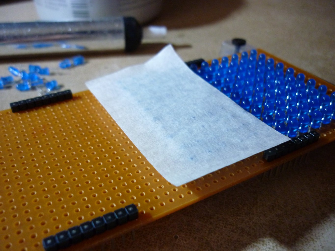
Step 2: Prepping the Circuit Boards and the LEDs
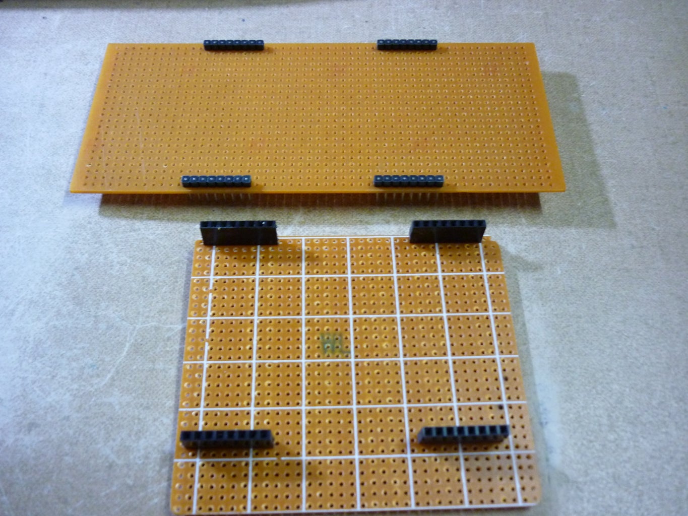


I started the build by soldering the header pins to my circuit board and I also trim the leads of the LEDs to be shorter. You can test the LEDs individually but it would be a waste of time so I skipped that and then replaced the broken ones after soldering.
Step 3: Assembling the LED Matrix


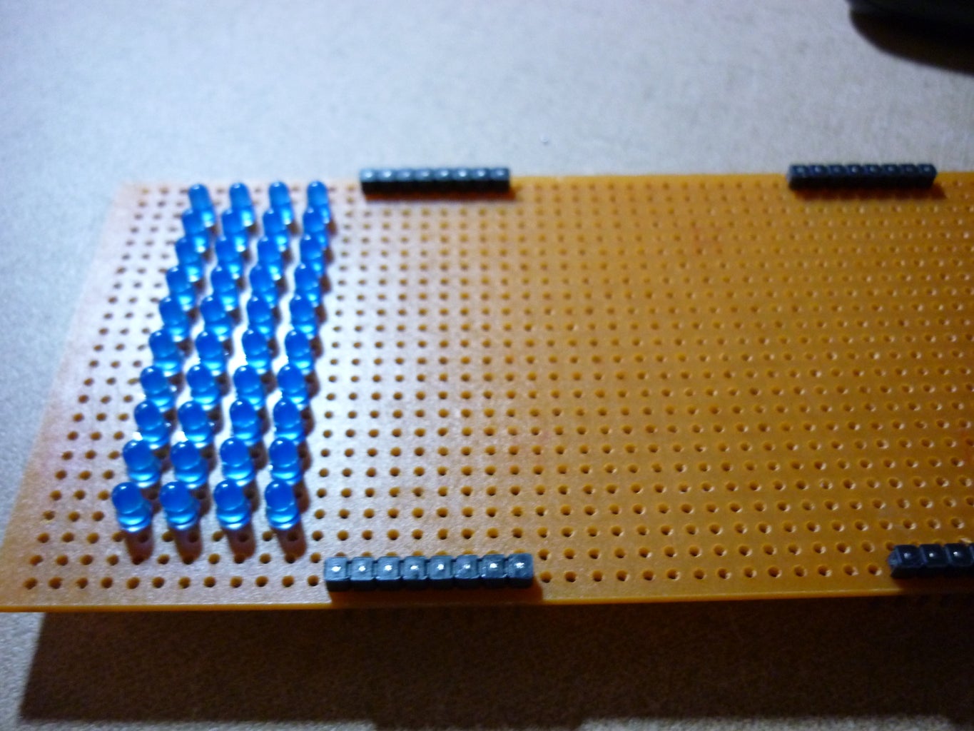
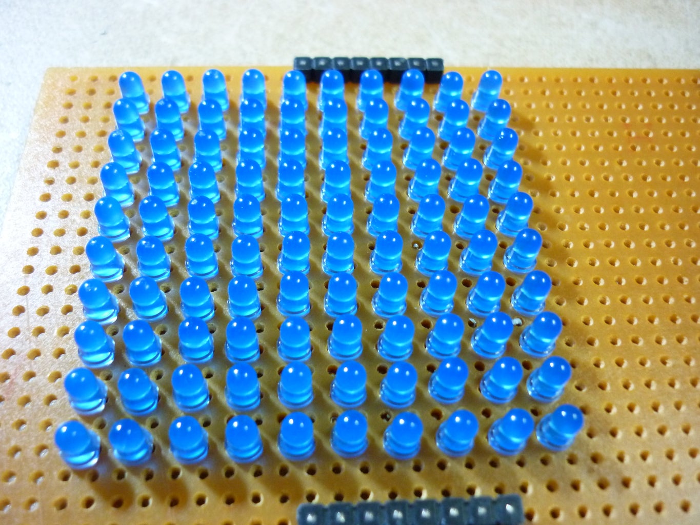


The LED Matrix are made with their anode connected to form 24 rows while the cathode are connected to form 10 columns. The rows are soldered together by bending the anode to the next LED in the row and soldering them together...
Step 4: Wiring the Matrix to the Header Pins

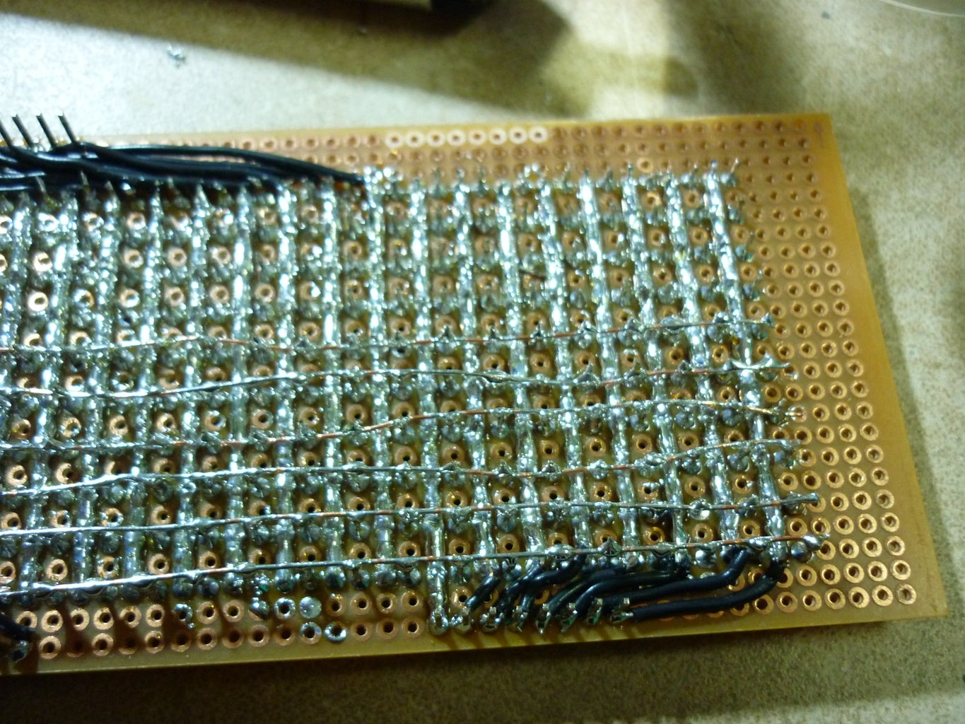

Wire the LED matrix's row and column to the header pins noting their position so they can be wired to the correct place later...
Due to my miscalculations I had added another header pins to elevate the Matrix Board so it wont touch the components on the Controller Board.
Step 5: Assembling the Controller Board
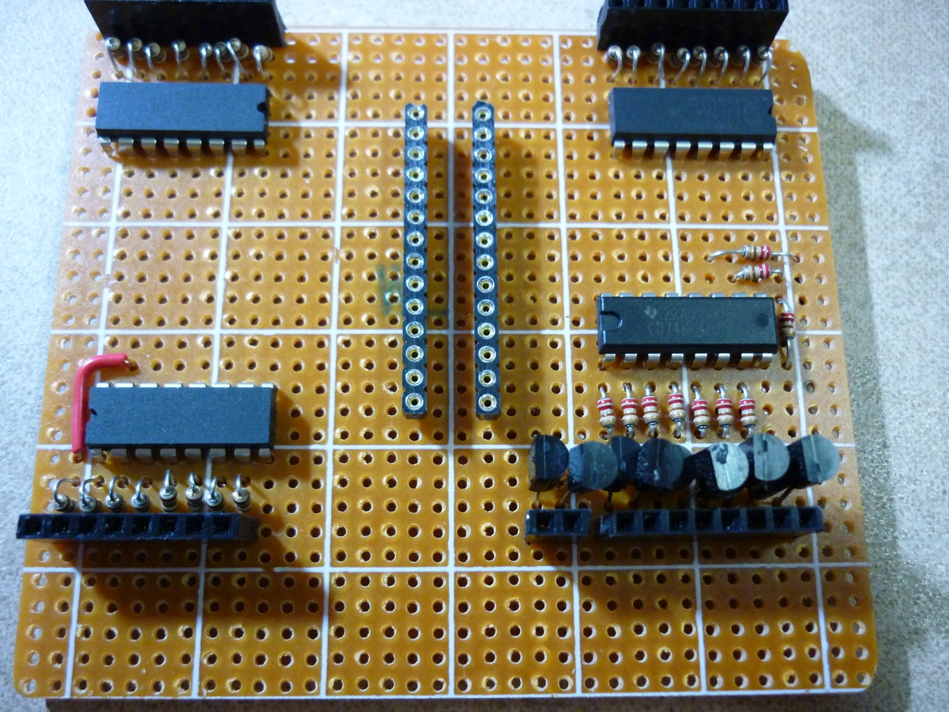

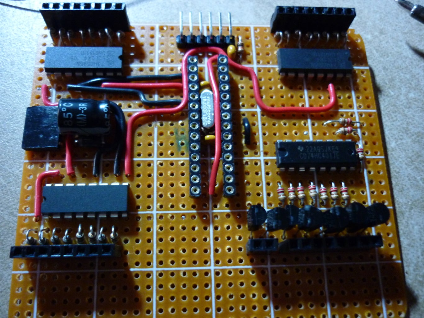

I start assembling the components by placing the MCU in the middle and the rest of the IC's in their respective places, near to the header pins. I connected the 4017 counter to the transistors with warping wires. My layout is not the best so if you are building this try not to follow mine, it's very troublesome. But at least in the end it works... The transistors are connected together but their height are alternated(1:lower, 2:higher, 3:lower, so on) to conserve space.
After everything is done, check for shorts, connection error and you're ready to go!
Step 6: Programming the Microcontroller
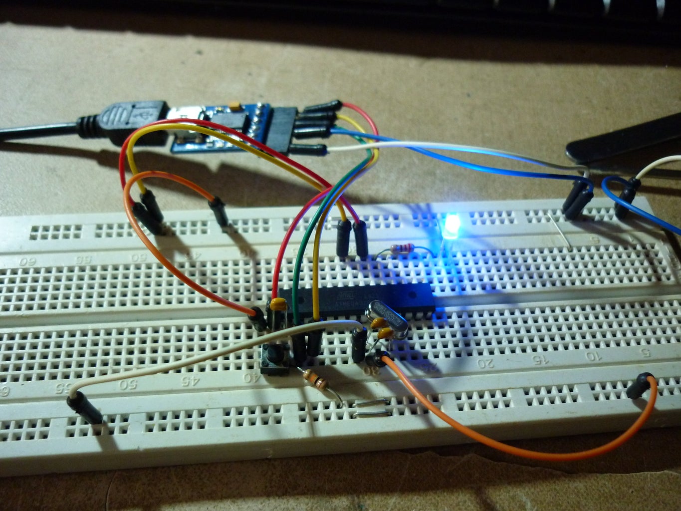
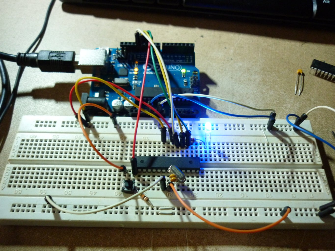

As my chips are blank from element 14 so I used ArduinoISP to flash the Arduino Uno bootloader and used the FTDI chip to upload the Blink sketch to see if it works. And of course, it works. After that I plugged everything together (MCU to socket and matrix board to controller board.) and programmed the main sketch into the board using the FTDI chip. AND IT COMES ALIVE!!!!! The MatrixLoop file is the main file took from Syst3mX's instructables and partially modified to suit this board. The SerialFont is also the same but I've modified it to use SoftwareSerial and connected a HC-05 bluetooth module to it.

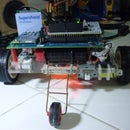
Step 7: Optional: Battery Pack


I made a battery pack for the LED Matrix by using 4 18650 Li-ion batteries salvaged from a laptop battery(2 cells broke but the rest was okay) and connected a charging module and some header pins to them.
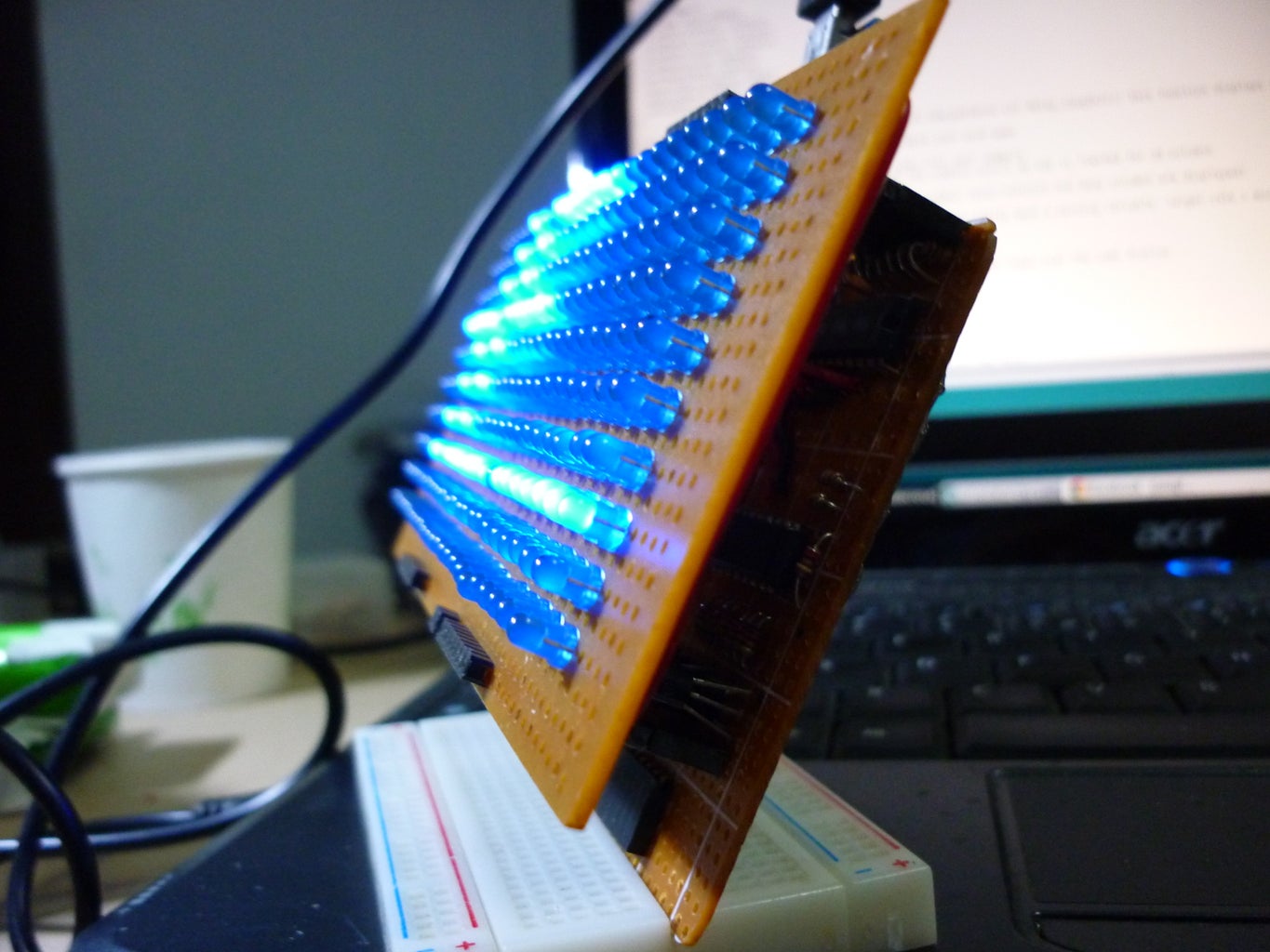
Step 8: Completed!


Now the whole thing is completed but there's still alot of place that we can expand, maybe a Internet connected message board? Email notifier? Graphic Equalizer display? LED clock? The possibilities are endless! I still have quite a lot of things to improve from but I do have learnt a lot of things from this build.
I would like to thank:
Syst3mX for his instructables Make a 24X6 LED matrix
and
astroboy907 for his instructables Make a giant LED sign! (24x8 Matrix)
Thank You! Without those instructables I wouldn't have completed this build.
I would also like to thank
Ladyada from Adafruit Industries. You've indirectly supported me with your Ask an Engineer show!
and You, the readers/community. Thank you for supporting me!
Do correct me if I've did something wrong so I can improve and do more!
Do vote for me if you think my build is great! Thanks!
Step 9: Afterthoughts?


After building the controller board, I've met a few problems and some OCD's ... Sometimes the IC pins of the MCU won't touch the contacts of the socket so the matrix does not display.... and all the 20 AWG wires used as jumpers are so annoying so I took everything apart and rebuild it and exchanged all the non power cables with warping wire, leaving the power and ground connections with 20 AWG wires. I also added 2 LED's (one on pin 13 and another on a free I/O pin) and also 4 buttons as inputs.Now the board looks neater and more professional(teehee). Lastly, an ICSP header was also added for programming bootloader without needing to remove the chip.
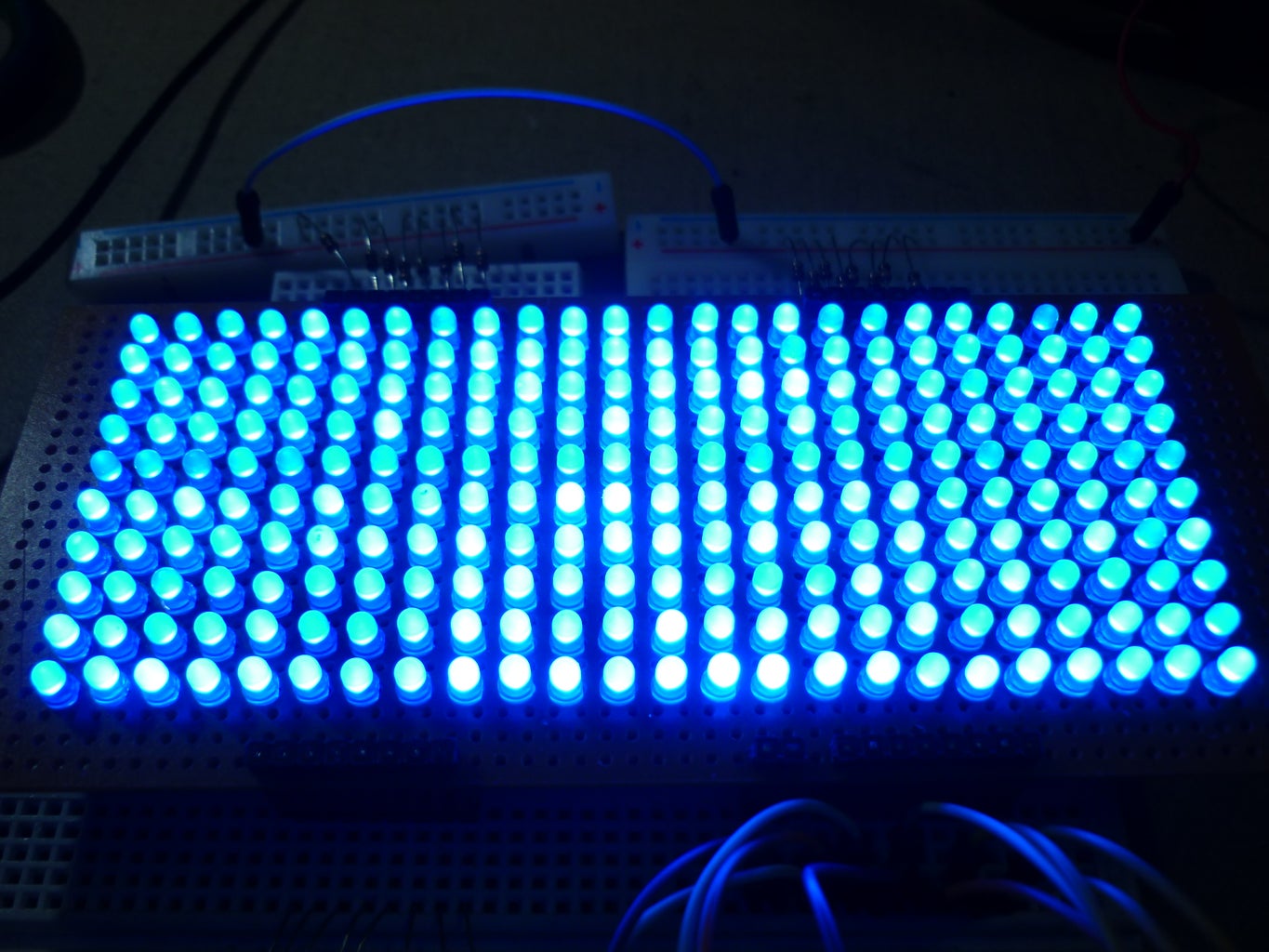
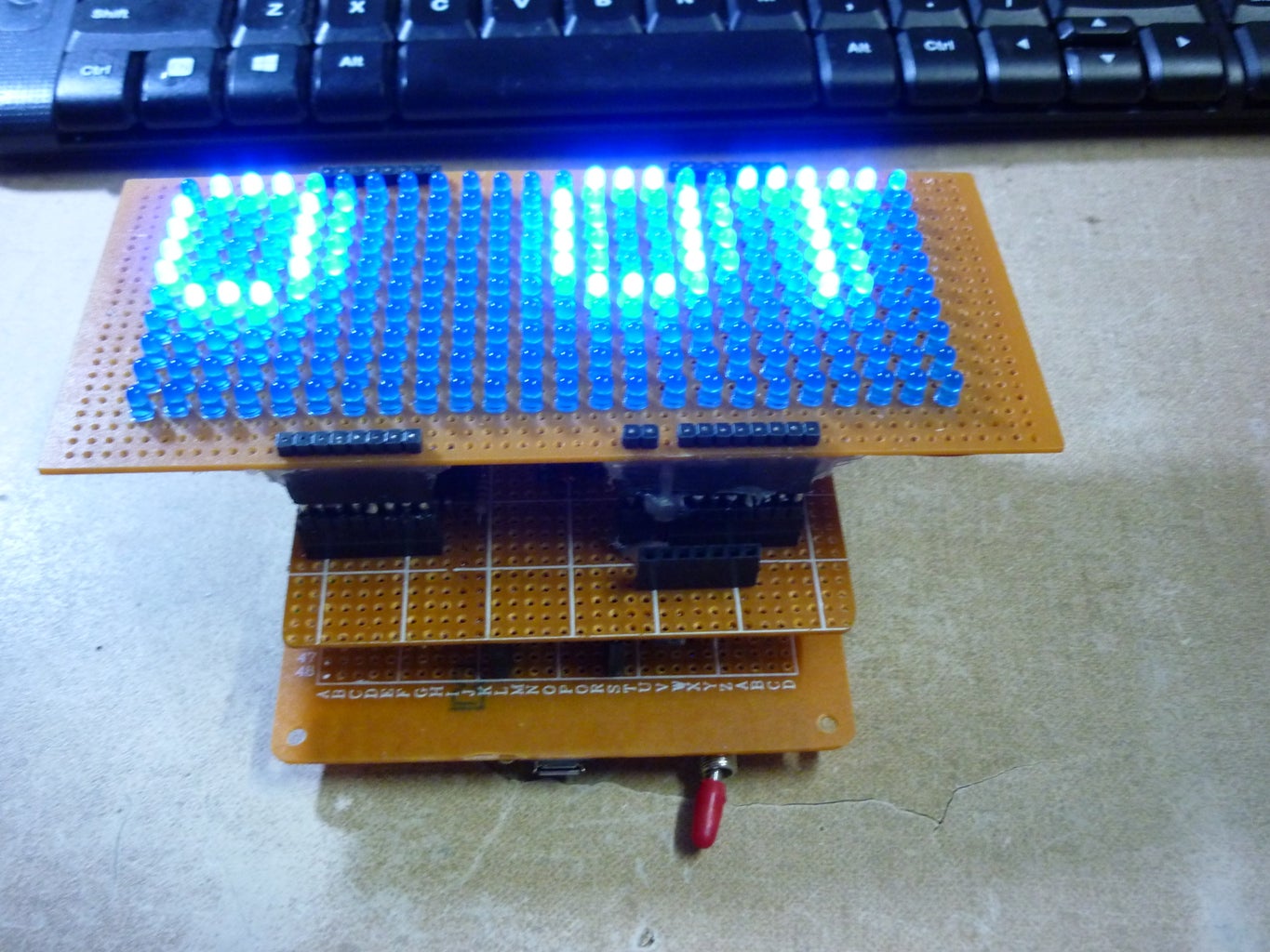
I've also added some pictures of all the LED's on which is taken in a dark environment... It's not as bright as it seems in the picture.....

Participated in the
Hand Tools Only Contest

Participated in the
Tech Contest

Participated in the
Microcontroller Contest


![Tim's Mechanical Spider Leg [LU9685-20CU]](https://content.instructables.com/FFB/5R4I/LVKZ6G6R/FFB5R4ILVKZ6G6R.png?auto=webp&crop=1.2%3A1&frame=1&width=306)


