

Introduction: Big Counter (2.75" Display)
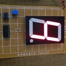


2.75" 7-Segment LED Display Counter 0-9 is a project based on cmos technology to operate correctly a 7-Segment LED Display of 6.8 V. The IC 4026 counter chosen is a practical counter operates without decoder, and with help of an IC 555 timer: the project can be completed.
Step 1: Bill of Materials


1 2.75" Common cathode 7-Segment LED Display
2 I C 4026 Counter
3 I C 555 Timer
4 16 Pin Socket
5 8 Pin Socket
6 9 cm x 15 cm PCB
7 Electrolytic capacitor of 47 u F
8 10 K resistor
9 5 K potentiometer
10 7 x 470 Ohm resistor
11 9 V Battery snap
12 9 V Battery
Step 2: Schematic

Diagram schematic is vital its follow-up so that you can complete the project without any problem.
Step 3: Install the 7-Segment LED Display


When installing the LED display, you can also insert the 16 pins socket into the PCB.
Step 4: Install the Resistors of 470 Ohm


Install the resistors of 470 Ohm between the LED display and IC4026.
Step 5: Insert the 8 Pins Socket


When inserting on the PCB the 8 pins socket, you can also connect the common cathode display pin to the pins V(-) from IC 4026.
Step 6: Installing the Capacitor & 10 K Resistor


When installing the capacitor and 10 K resistor, you can also complete the common negative from the circuit by connecting the negative terminal from capacitor to pin 1 from IC555 timer and to pin 2 from IC4026. Then, you can connect the positive terminal from capacitor to pin 2 from IC555 timer and to pin 6 from itself. On pin 6 from IC timer also join a terminal from the resistor of 10K to leave free the other terminal of the resistor.
Step 7: Install the 5 K Potentiometer


When installing the 5 K pot and making the connections to IC 555 timer, you can also connect the pending terminal from 10 K resistor to pin 7 of the same IC. In this step, you can complete the common positive from the circuit.
Step 8: Install the Battery Snap

For installing the battery snap, you need to take the common positive & negative terminals and connecting them to red & black wire from battery snap respectively.
Step 9: Completing the Project


For completing the project, insert each integrated circuit into its socket and the battery into the battery snap.


