

Introduction: 4 Bits Binary Counter Up/Down
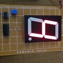


The counter is a 4 bits binary counter up/down. That is, this counter can counter from 0 to 15 or from 15 to 0 because it counts either up or down. The project is a binary counter made with a 4029, a 555, and 4-10 mm LED mainly by using a double dip slide switch to select up or down.
Step 1: Bill of Materials
1 PCB 5 cm x 7 cm
2 4 x 10 mm LED
3 4 x 330 Ohm resistor of 1/8 W
4 1 Socket I C 16-pin
5 1 Socket I C 8-pin
6 I C 4029
7 I C 555 timer
8 47 u F capacitor
9 10 K pot
10 10 K resistor of 1/8 W
11 2 position slip dip switches on/off
12 9 V Battery Snap
13 9 V Battery
Step 2: Schematic
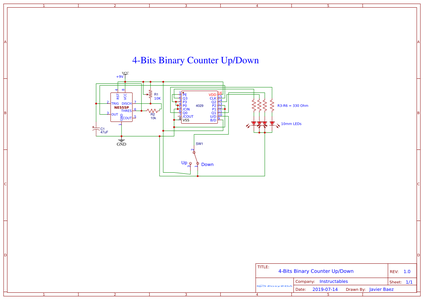
Follow the diagram schematic so that you can conclude the project successfully.
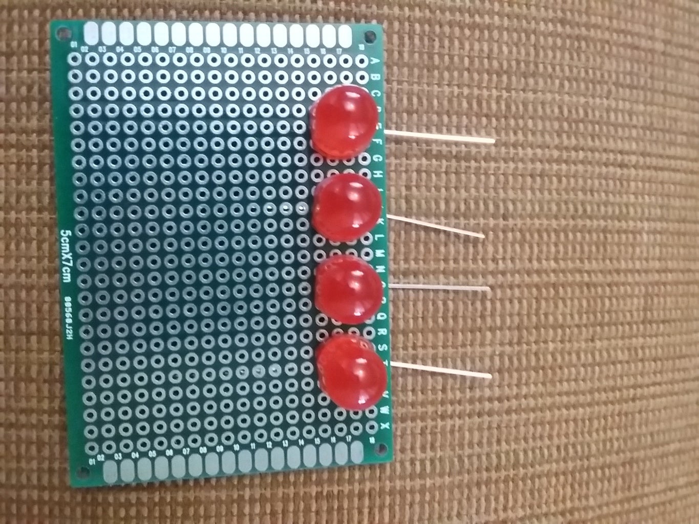
Step 3: Identifying the LEDs


Identify the LED polarity, and so you can work freely.
Step 4: Inserting the LEDs
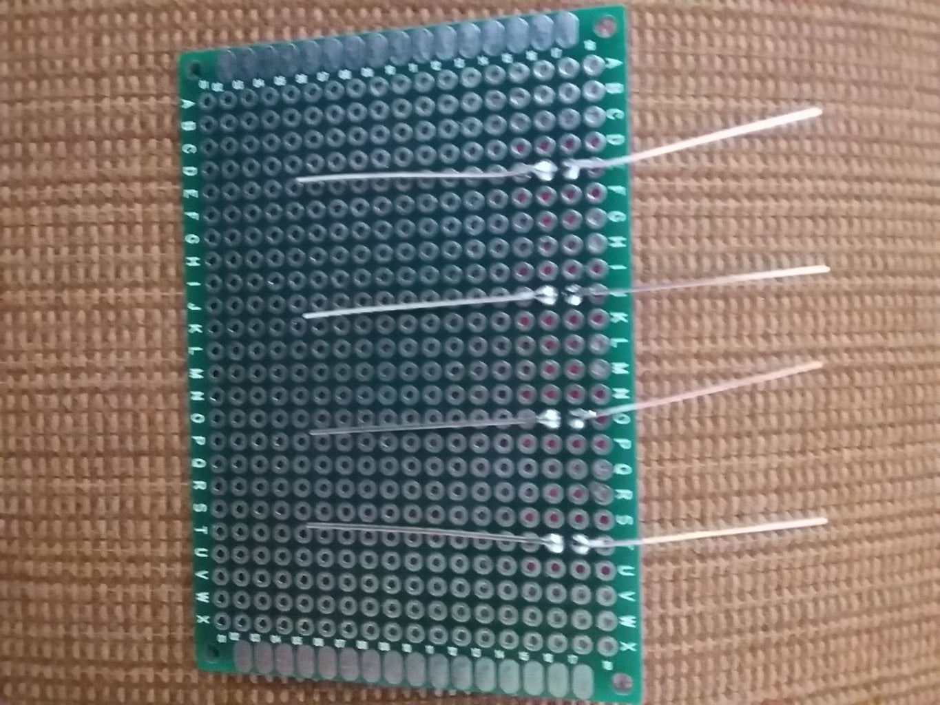

After inserting the LEDs into the PCB, fold their terminals and solder them.
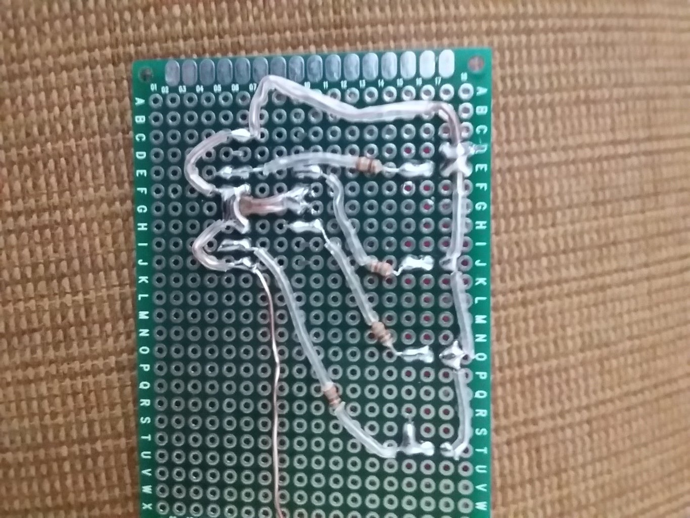
Step 5: Installing 16-Pin Socket


Insert the 16-pin socket and solder its output pins to the resistors. Note that you are leaving free the common negative of your circuit.
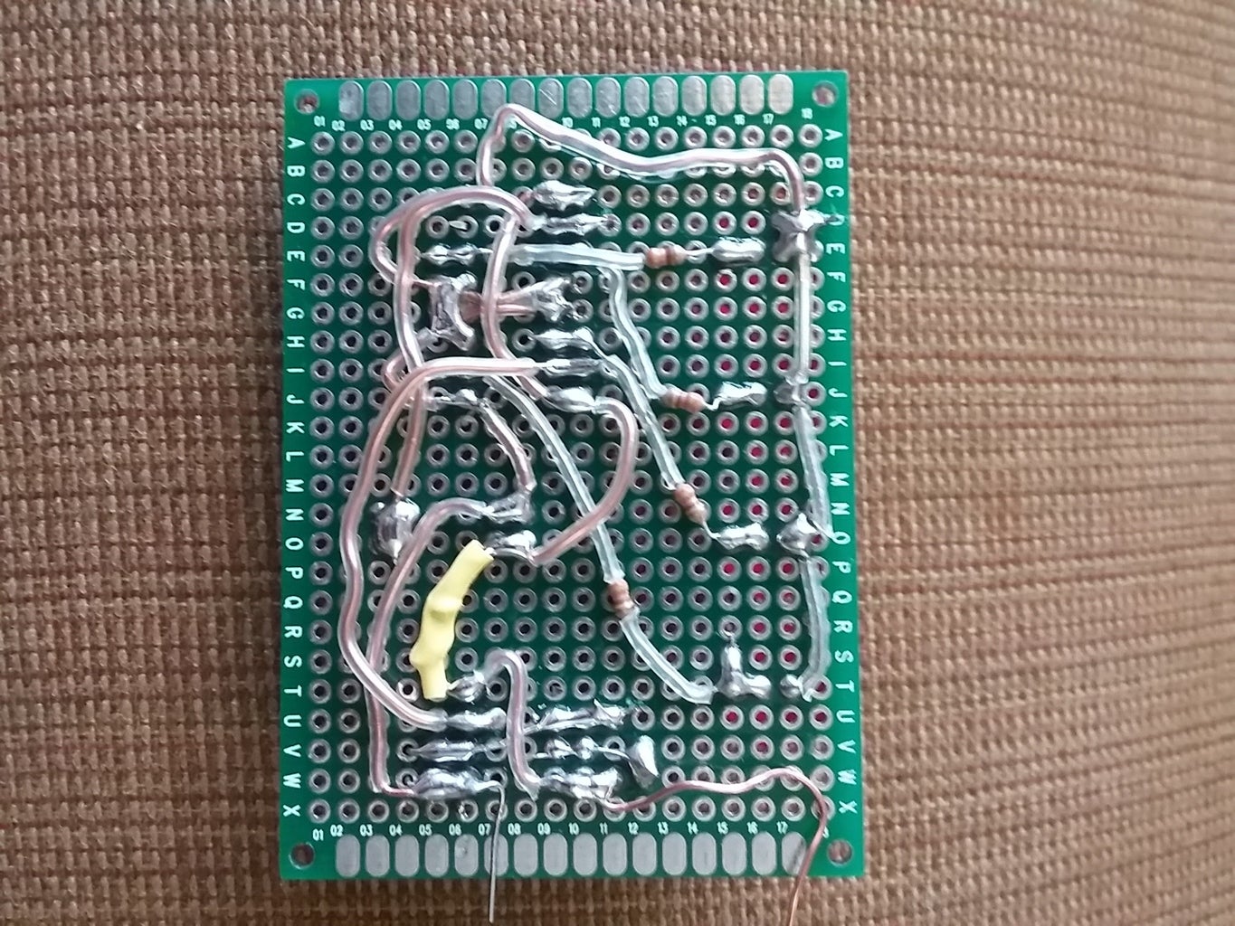
Step 6: Connecting the Common Negative


Once connected the common negative from the LEDs to IC4029, you can also establish the common positive of this circuit.
Step 7: Installing the Dip Switch


It's very important this step because you will be establishing the Up/Down of your counter. The previous event is possible if you connect the common negative terminal to a pin switch and the other switch its terminal to the common positive terminal. The rest of the pin switches will be connected to pin 10 of IC 4029, and you will leave free the common positive and negative terminals too.
Step 8: Install the 8-Pin Socket


Install the 8 pin socket and the capacitor, and you can also the common negative terminal to the 8-pin socket.
Step 9: Install the Pot and Resistor of 10K


Installing both the pot and resistor of 10 K , you can finally connect the common positive terminal too.
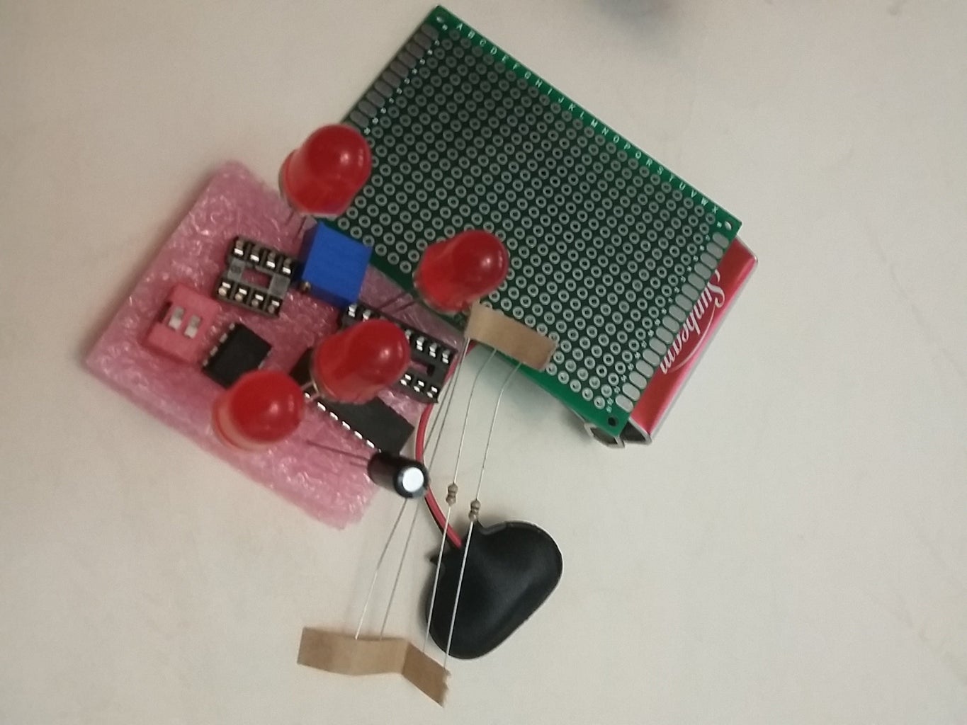
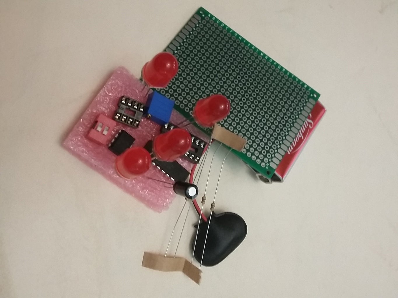
Step 10: Completing the Project


For completing the project, solder the battery snap and insert the IC4029 counter & IC555 timer.
Step 11: Probing the Project


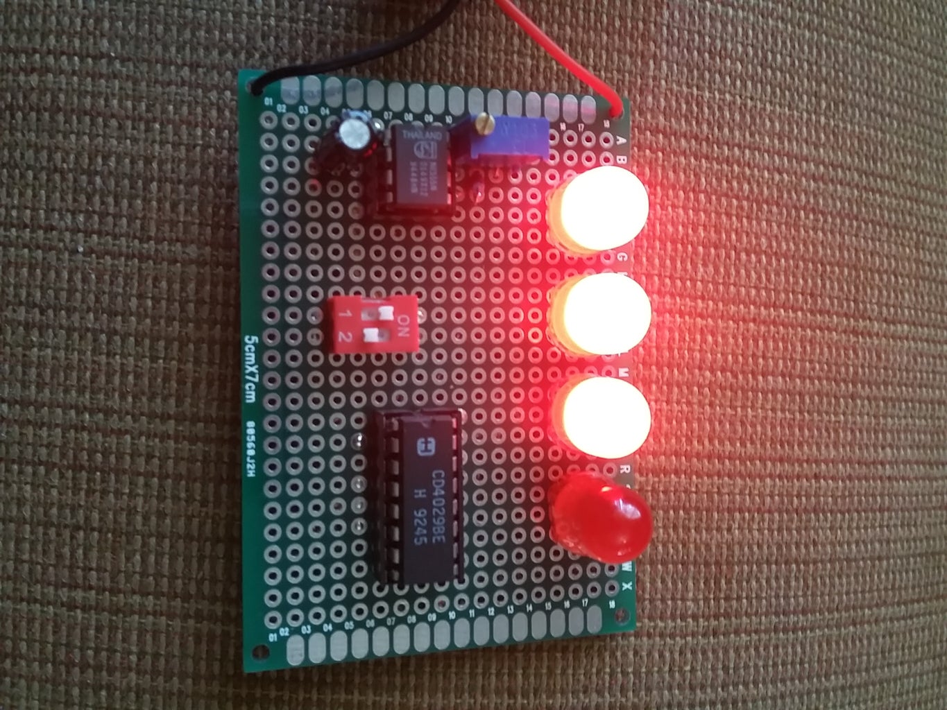
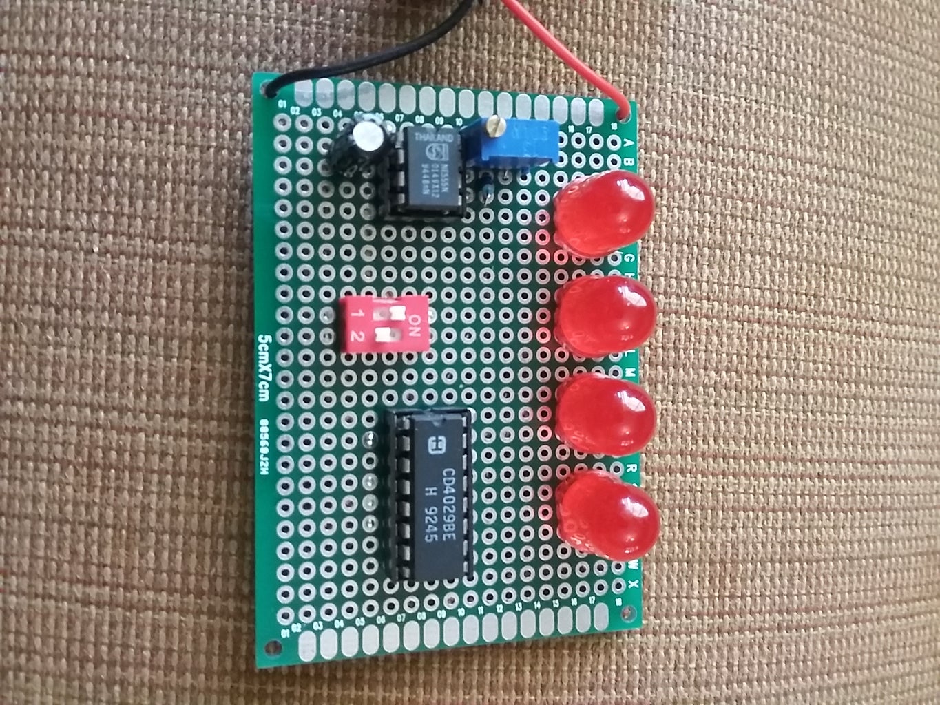
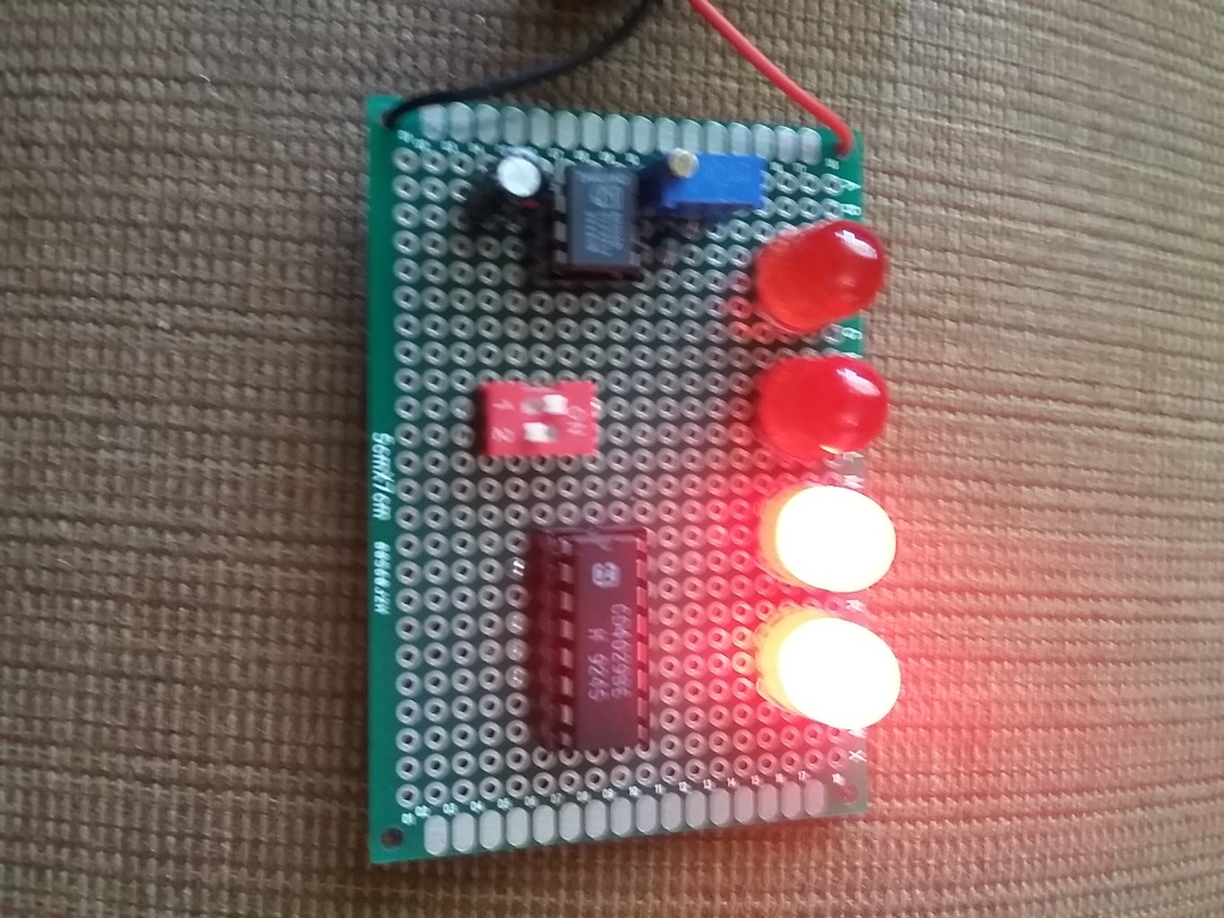

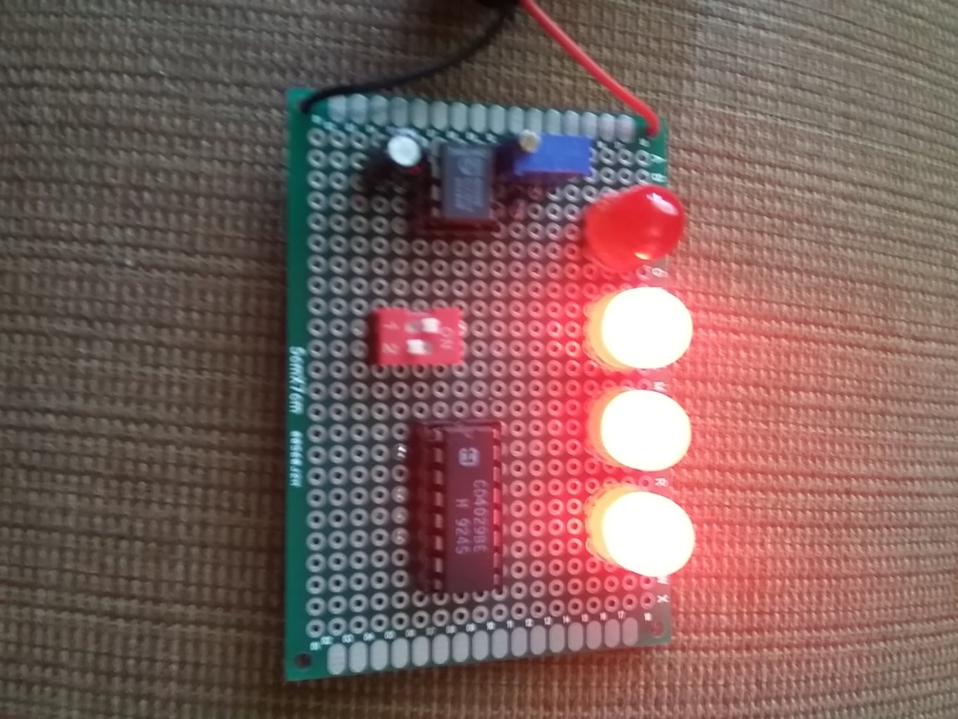
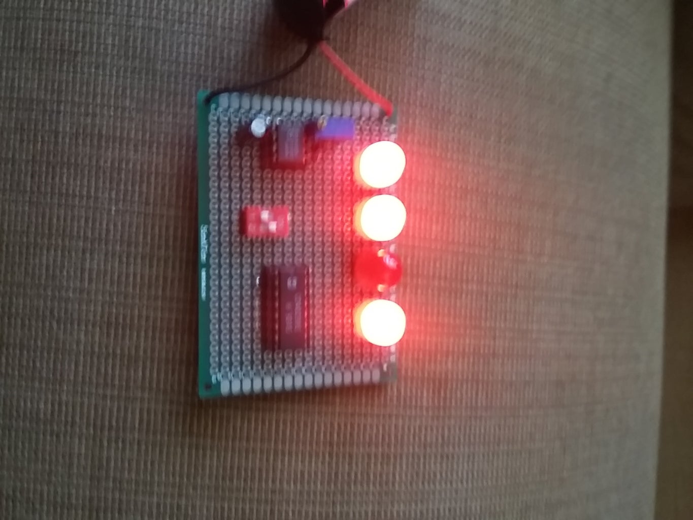

For probing the project, insert the battery in the battery snap and select up or down on the switch by being right or left respectively.


