

Introduction: 3D Printed Arduino Rotating Table With 28BYJ-48 Stepper


This project shows how to make a 3D printed Rotating Table using Arduino and a hobby stepper motor. Take a look at the video and see what a simple project can do! This is a low budget and simple set up Rotating Table for product shots. I will definitely use this rotating table for video shoots for my own channel.
Supplies


The project needs inexpensive components. You can easily find the components listed below in the market.
- 1x Arduino Nano V3 microcontroller
- 1x 28BYJ-48 hobby stepper motor
- 1x ULN2003x stepper motor driver
- 1x 5V power supply
- 4x 608 bearing (8x22x7mm)
- 2x Screws to mount the motor
- 1x On/Off switch
- Miscellaneous jumper wires
Step 1: How It Works?
28BYJ-48 Stepper Motor and ULN2003 motor driver were used in the project. On the microcontroller side, an Arduino Nano V3 version was preferred. Besides the breadboard circuit, a printed circuit board (PCB) was designed for a more useful prototype. The making stage of the project is shown in the video step by step.
Step 2: Download and Print 3D Parts
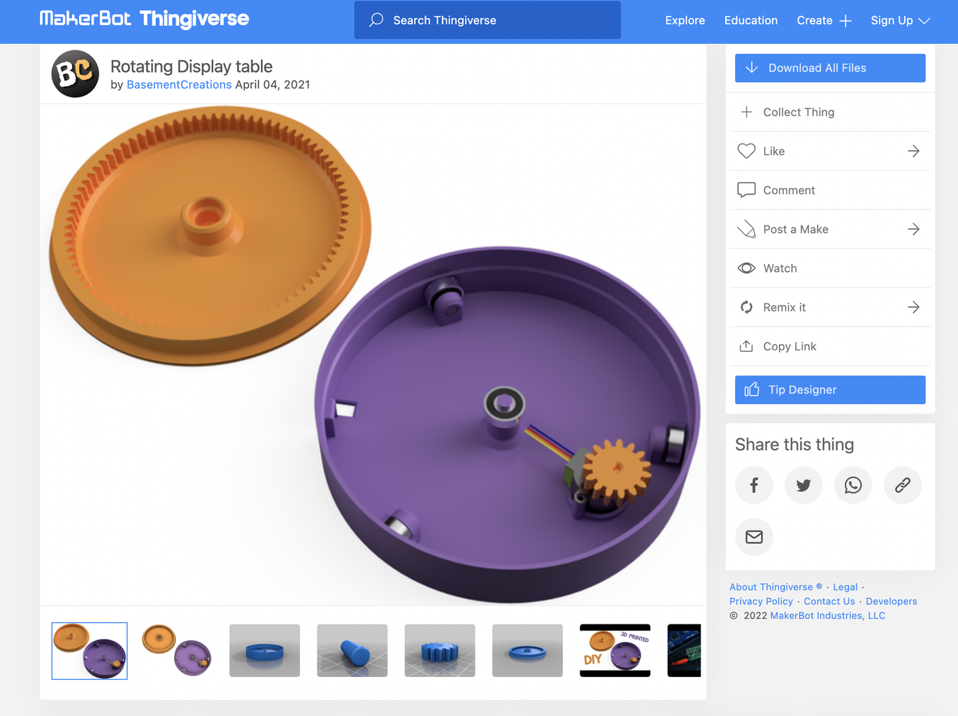
The 3D models were designed by BasementCreations and shared on Thingiverse. Download the STL files of the 3D models from the link below and print them with the help of a 3D printer.
Rotating Table 3D Parts - https://www.thingiverse.com/thing:4817279
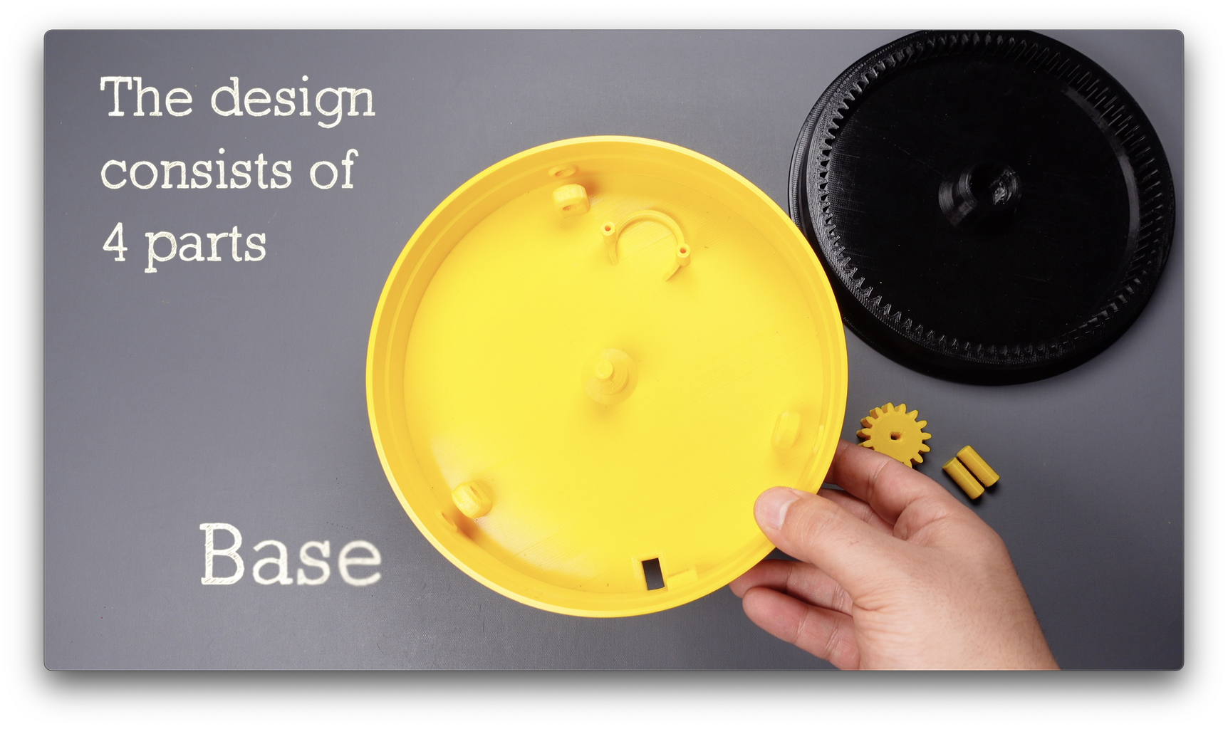
The design consists of 4 parts base, top plate, motor gear and pins for fixing the bearings.
Step 3: Assembly of Parts


A total of 4 608 bearings were used in the project. Place 3 bearings on the base with the help of pins. If there is a break in the pins, you can use bolts of the same thickness. We will use the last bearing for the top plate. Place the last bearing in the center of the top plate. 1 hobby stepper motor was used in the project. Attach the motor gear to the stepper motor, then fix the stepper motor to the base using 2 screws.
Assembling the 3D parts is that simple, we'll build the circuit in the next step.
Step 4: Breadboard Circuit

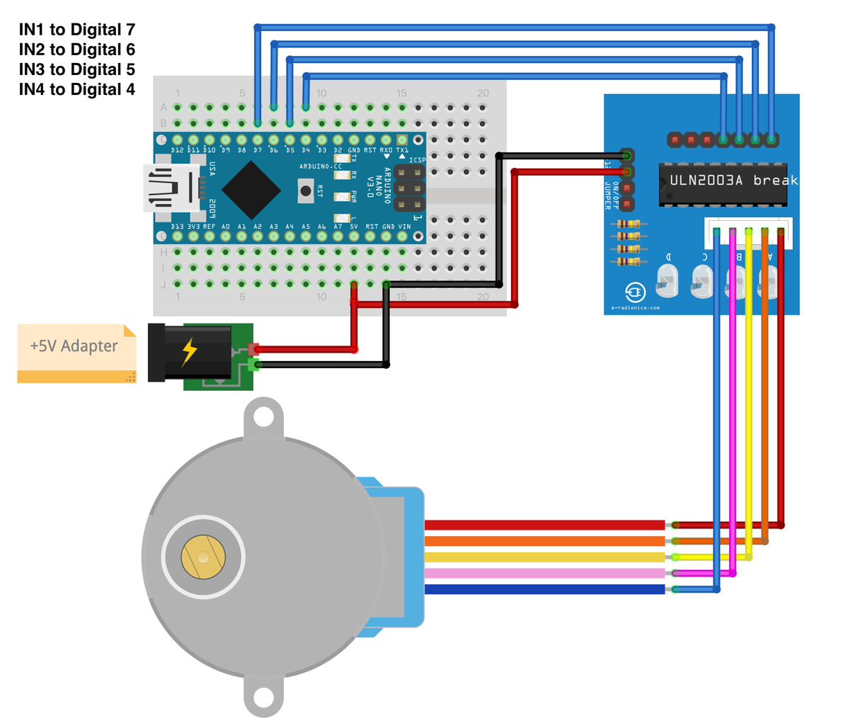

The circuit is simple to set up. Build the circuit by following the links in the shared schematic. 28BYJ-48 Stepper Motor and ULN2003 motor driver were used in the project.
28BYJ-48 Stepper Motor
One of the inexpensive way to learn about stepper motors is to use 28BYJ-48 stepper motors. They usually come with an ULN2003 based driver board which makes them super easy to use. The 28BYJ-48 is a 5-wire unipolar stepper motor that runs on 5 volts. One of the best things about these motors is that they can be positioned accurately, one ‘step’ at a time. The other advantage is that they are relatively precise in their movement.
The power consumption of the motor is around 240mA. Because the motor draws too much power, it is best to power it directly from an external 5V power supply rather than drawing that power from the Arduino.
The ULN2003 Driver Board
The motor usually comes with a ULN2003 based driver board. The motor usually comes with a ULN2003 based driver board. The ULN2003 is one of the most common motor driver ICs.
The board has a connector that mates the motor wires perfectly which makes it very easy to connect the motor to the board. There are also connections for four control inputs as well as power supply connections.
The pin connections of the motor driver to the Arduino Nano are as follows:
IN1 to Digital 7
IN2 to Digital 6
IN3 to Digital 5
IN4 to Digital 4
Step 5: Printed Circuit Board (PCB)


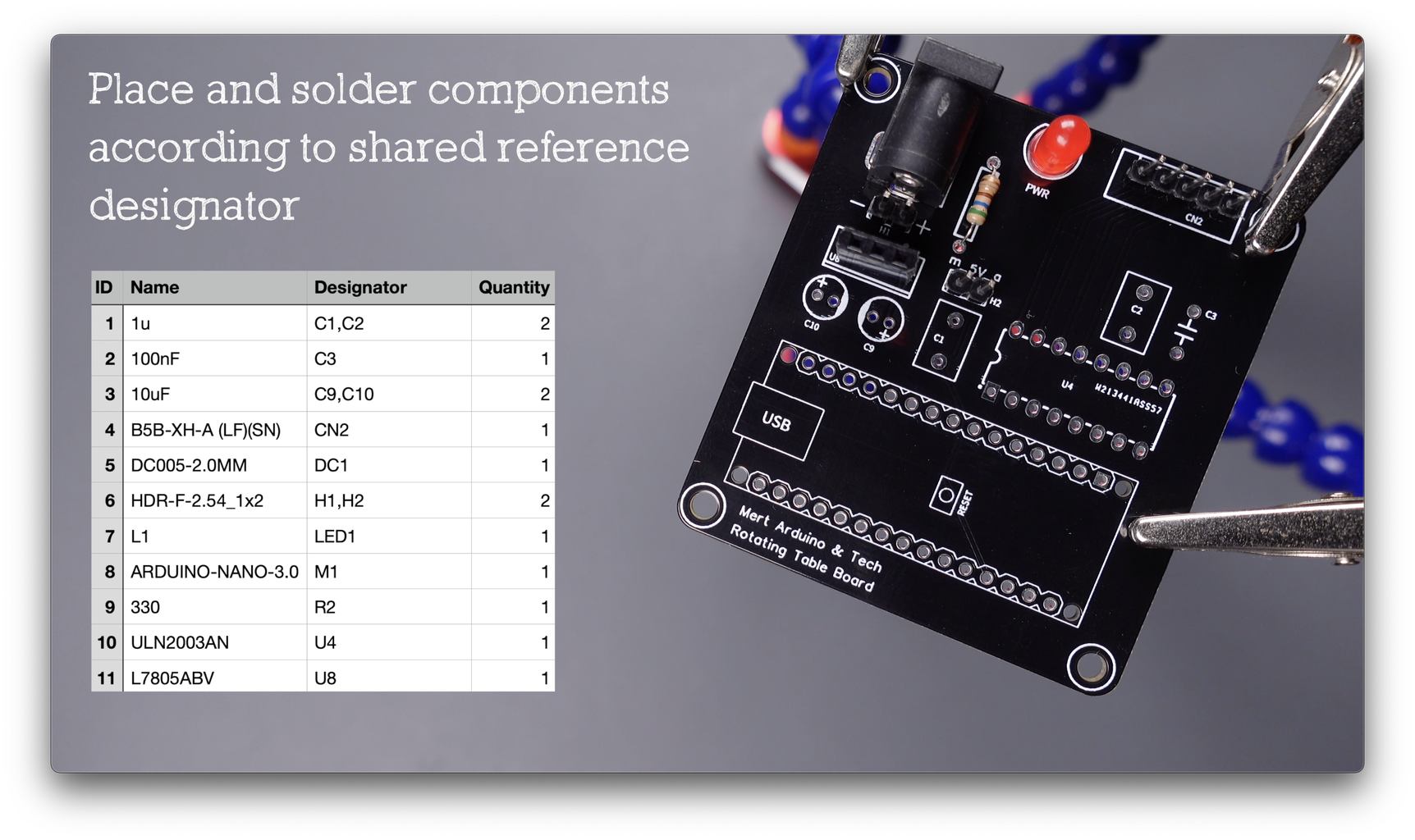
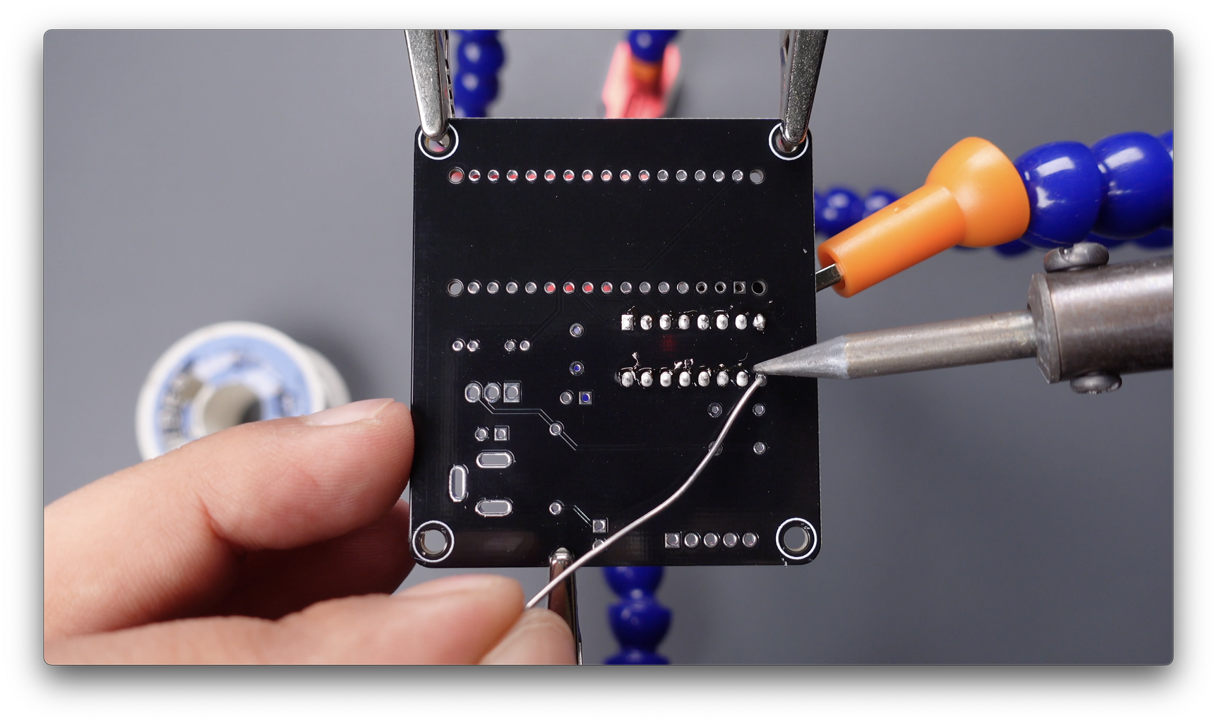
After building and testing the breadboard circuit, I designed a printed circuit board to turn the project into a useful prototype. Printed circuit boards are plates with conductive paths on the surface for mounting electronic circuit components.
To get the PCBs, simply upload the shared "Gerber file" from https://www.pcbway.com/project/shareproject/ to PCBWay and create an order. High-quality PCBs will arrive in a few days depending on the shipping address.
3D Printed Arduino Rotating Table Board needs a few components. Place and solder components according to shared reference designator.
Step 6: Source Code

Upload the shared stepper-test.ino source code. If your motor runs to the wrong direction, change the order of the numbers in code as: int port[4] = {4, 5, 6, 7};
Also, no library is required for the source code.


