

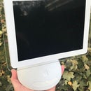
Introduction: 3D Printed IMac G3 Mini - Fully Functional Hackintosh Powered by Intel NUC


The Big Picture
I have a certain fondness for Small Form Factor (SFF) computers. Don't get me wrong, I also love large screens and multiple monitors. There is just something about certain Apple designs that calls to me to either mod or shrink them. I was working on a mini computer case based on a NUC, and the NUC seemed to stop working, so I bought a spare... and then 4 more spares. Then I needed more projects to put the NUCs into. As I juggled around ideas for these projects, I came across some clear 3D media that I thought would match "Ruby Red", but later found out it was closest to Apple's Strawberry. This is the story of one of those builds: A miniature iMac G3 (original iMac) reduced to 38%.
Supplies


List of 3D parts (3 colors needed: Black, Clear, Primary color)
Lower Cover (clear)
2 Speaker Grills (primary color)
Front Outer Bezel (clear)
Front Inner Frame (clear)
Screen Bezel (black)
Screen controller holder (any color)
Upper Colored Cover (primary color)
2 Apple Logos for top and rear (primary color)
2 Internal Side supports and antenna mounts (clear or primary)
Lower Frame (clear or primary)
2 PSU mounts (clear or primary)
Side Panel Port Cover (clear)
Top Handle cover (clear)
Top Handle insert (primary color)
Power Button (clear)
4 feet (clear)
Kickstand (primary)
Port Cover (clear)
Parts (not 3D printed)
5.5 LCD and driver board, HDMI input
Intel NUC 4x4 motherboard with power supply (most 4x4 models should work, Skull Canyon is too large)
C7 power socket
C8 power cord
1 miniature 3mm LED, your choice of color but matching your primary looks better
2 momentary push button switches
1 small piece of perf board (DIY circuit board)
3.5mm stereo female audio jack (salvaged from an old tower PC)
3.5mm stereo male plug with wires (I salvaged an old set of wired earbuds)
a pair of very small speakers (salvaged from a laptop)
Dual USB2 panel (salvaged from an old tower PC)
misc wires
small header connectors to the NUC (they vary in sizes)
3D printer media (PLA, PETG, ABS, whatever you prefer, appropriate colors)
mini amp (PAM8406 5Wx2 5V)
25+ small screws (I salvaged from old spinner hard drives, and ordered 20 2.5mm and 3.0mm x10mm)
Some tiny washers as spacers
a very short HDMI cable (I used a flat ribbon cable with adapters)
Transformer or step-down to 12v for the display power
Aluminum foil tape (self adhesive)
4 small rubber feet (kitchen cabinet bumpers work well)
Tools & Resources
3D Printer with slicer software (Raise3D IdeaMaker, Ultimaker Cura, etc)
Soldering Iron
Hot Glue Gun or other adhesives
Power Drill
Drill bits
Taps (M2.5 and M3)
Clippers, files, sandpaper (80-3000grit) for cleaning and smoothing 3D printed parts
Heat source (heat gun, solder reflow workstation, mini-torch) to correct/adjust or form already printed parts
3D software in case you need to modify the 3d files to fit your NUC (Fusion360, AutoCAD, Blender, FreeCAD, MeshLab, MeshMixer, etc)
Time and Patience
Step 1: Modeling


There are a lot of great sites to find free 3D models out there. There are some that are exceptionally detailed and some that are so rough they are good for background CGI only. Some Apple products have plenty of models available, and some are more rare. Finding a detailed iMac G3 model was difficult. I found plenty of low resolution or ugly models and a couple finer looking ones that required a purchase. I finally broke down on trying to find a free one and purchased what I thought was a highly detailed model. It was detailed for 3D rendering, but horrible for 3D printing. I spend many hundreds of hours (if not weeks) converting and rebuilding pieces so they would 3D print correctly. I primarily used Lightwave 3D as my modeler. Often I took STL files back and forth between MeshMixer, MeshLab and Lightwave for certain functions that one of the other programs didn't have. Are there better tools? Likely. Are these models perfect? Absolutely not.
I did NOT have access to an actual iMac G3 when I started this project, so I had no idea if my model was accurate or not. Half way through this project, I visited my local FreeGeek shop and found a pair in the same colors I had, but I only purchased the strawberry one.
Here are all my 3D parts in STL format for you to print.
Attachments
 iMacG3_r38-AppleLogo-2.stl
- iMacG3_r38-Feet-2b.stl
- iMacG3_r38-FrontInnerFrame-8te.stl
- iMacG3_r38-FrontOuterBezel-9k2e.stl
- iMacG3_r38-Grills-3d.stl
- iMacG3_r38-InternalSideSupport-2f2e.stl
- iMacG3_r38-Kickstand-3.stl
- iMacG3_r38-LowerCover-8j3.stl
- iMacG3_r38-LowerFrame-f6k5.stl
- iMacG3_r38-PortCover-2f3e.stl
- iMacG3_r38-PSU-1d1.stl
- iMacG3_r38-PSU-1d2.stl
- iMacG3_r38-PwrBtn-2c.stl
- iMacG3_r38-ScreenBezel-2h2.stl
- iMacG3_r38-ScreenControllerHolder-2d4.stl
- iMacG3_r38-TopHandle-2c.stl
- iMacG3_r38-TopInsert-2c4e.stl
- iMacG3_r38-UpperColoredCover-1b.stl


Step 2: What Size Is This?


A few factors played into the final size for this project:
1. The print volume of my 3D printer (Creality Ender 3 Pro).
2. The motherboard size (Intel NUC is 4x4 inches).
3. The screen size. This was adjusted based on availability and possible sizes from 1 & 2.
As I began developing the model, I started with 40% and later went down to 37%, but finalized my size on 38.5%. While the screen size is 5.5 inches and the original is 15 inches, that gives me 36.6%, but I needed some extra space for the motherboard and additional components and connectors inside the case, so I had to increase it ever so slightly.
Step 3: Trial and Error


You can model with zero tolerance, but 3D printing needs a little bit of gap. Sometimes you have to deal with warping, shrinkage, and sloppy printing. I try to only print small sections of pieces that I perceive will have problems, to try them out and adjust them before I make a long 12+ hour print. If you forgot one mount, hot glue can solve it, if you forgot to remove something, clippers, drills, sanding, etc. will solve it.
3D print all parts. This is the most time consuming, but gives you time for the other steps. Deburr and sand as needed. Work your way through all the grit levels if possible. I used 80, 180, 320, 800, 1500, and 3000 grit. Use the higher grits with water to improve workflow. When completed sanding, you should clean off all dust. Then, I chose to use a light coat of GooGone (citrus based) to give the finish a little sheen.
Step 4: Testing Before Final Assembly


Make sure you assemble all the electronics parts and test everything out, before you mount it inside the 3D printed shell. Installing software and patches as well as any hardware modifications can be a difficult task if you have to disassemble everything and rebuild it.
Near final assembly, I discovered that my headphone jack had malfunctioned and needed to be replaced. I am glad it was not completely assembled when I discovered this flaw.
Step 5: Assembly: Front Inner Frame


-Mount the dual USB into the Front Inner Frame (FIF)
-Create an extender for the headphone jack with the male plug wires and the female jack, when the external jack is occupied the sound should go to the headphones, when the jack is empty, the sound should go to the speakers (use an internal amplifier if needed). If you are including a microphone, make sure this is wired in as well.
-Create wire leads with header for your NUC to the dual front USB ports.
-Install the microphone to the top of the FIF with some hot glue, aligning the mic hole to the FIF top hole while leaving enough room for the screen bezel
-Mount the screen into the bezel
-Mount the screen controller to the bezel and install the controller board and cables
-If audio amplifier used, mount it to the screen controller arm with two screws by drilling a couple small holes for the screws
-Mount the bezel into the Front Internal Frame (FIF) with 4 screws
-Solder wires to speakers and install into the FIF
-If amp used, solder speaker wires to amp and amp to audio jack, if no amp, speaker wires to audio jack
-Cut a 5x13 holed piece of 0.10 perf board. Drill two holes for mounting screws. Mount the LED and two pushbutton switches. Install wire leads and header to match your NUC for the power button and the front LED. The dual switches should be wired in parallel, so either activates the power connection.
-Cover any parts you don't want to glow with aluminum duck tape
-Insert the power button piece into the FIF
-Install the power perf board into the FIF with 2 screws
Step 6: Assembly: Lower Frame


-My C7 power plug has the solder terminals sticking out the back, but we need them to be at 90 degrees to maintain a lower profile. Trim down the C7 plug so the terminals can be bent to 90 degrees, then bend them.
-Test mount the C7 power plug into the Lower Frame (LF) and carve it down so it fits inside the Lower Cover. Remove the C7 from the LF for the next PSU phase.
NUC power supply:
-Pry open the NUC power supply to remove the outer plastic cover. Carefully remove the outer shielding (aluminum shroud) and save it as we will reattach it later.
-Cut off the primary 19v output cord to about 6-8 inches from the end that goes into the NUC.
-Unsolder the 3-prong "Mickey Mouse" wall outlet connector.
-Prepare two thick wires for the new C7 power receptacle, and solder the C7 plug to the wires and the wires to the power supply L & H terminals.
-Solder the short 8" NUC power adapter back on, as well as wires for the 12V down-converter.
-Solder on the 12V downconverter and reattach the outer aluminum shell.
-Solder on a short 4pin header to power the LCD panel to the 12V down-converter.
-Mount the C7 power plug into the LF with 2 screws
-Mount the rear PSU support to the LF with 2 screws
-Mount the front PSU support to the LF with 2 screws
-If the PSU wobbles, zip tie as necessary
-Mount the 12v downconverter to the top of the front PSU mount with 2 screws
-Mount the NUC to the LF with 4 screws
Step 7: Assembly: Top Color Shell


-Mount the Top Handle Insert to the Top Handle Cover with two screws. This handle is only for aesthetics so hot glue the assembly to the primary shell from the inside
-Attach wireless antennas to the two Internal Side Mounts
-Attach the two Internal Side Mounts to the primary shell sides with 1 screw each
Step 8: Assembly: Lower and Front Covers


-Attach 4 feet to Lower Cover with 4 screws and attach rubber pads
-Install Kickstand to the Lower Cover
-Install the two speaker grills to the Lower Cover (hot glue - clear)
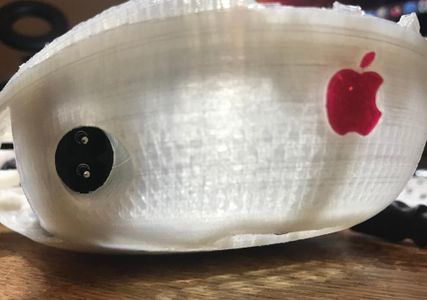
-Attach 2 logos to the exterior case
Step 9: Assembly: Final


-Place the FIF face down and lower the primary shell over it and attach the top two inner mounts with 2 screws and one outer center screw.
-Bring the LF upright against the primary shell and attach the 12v power to the display, then attach the LF to the shell with 8 screws (4 to the side mounts on the primary shell, 2 near the read of the primary shell, and 2 on the sides of the FIF near the speakers, see 3rd photo)
-Attach the NUC to the LF with 4 screws
-Attach wires to NUC (headphone plug, USB header, front LED and power button, amp USB power, antennas)
-Attach the port cover to the NUC with 1 screw
-Mount the Front Outer Bezel over the FIF by inserting the top two tabs first and then slowly pushing it down (it should flex but not break).
-Mount the Lower Cover by clipping the two tabs under the Front Outer Bezel mounts and swinging it closed. Secure with 3 screws.
-Attach the C8 power cable and test it out!
Step 10: Have a Small Amount of Fun!


Comparison
Original iMac G3:
266Mhz G3 Processor
4Gb 3.5 Hard Drive
32Mb PC-100 SDRAM
Tray loading CD-ROM
Two side USBv1.1
15" CRT Monitor
Ethernet 10/100
Weight: 35 lbs
MacOS 9.2.2
Mini iMac NUC:
1.6Ghz Intel Dual-Core i5-5250U
512Gb M.2 SATA SSD
16Gb DDR3L PC3L-12800
Two side USBv3.0
Two front USBv2.0
5.5" LCD Monitor
External mini-HDMI output
Wireless-AC 7265 + Bluetooth 4.2
Weight: 3 lbs
MacOS 13 Ventura

Runner Up in the
CNC and 3D Printing Contest


