

Introduction: 3D Printed Moire Illusion


I first saw this Moire illusion on Kickstarter and searching a bit brought quite a few more designs. Though none of them are open source, and most are built using wood and springs. Some of the notable ones are:
- https://www.kickstarter.com/projects/xercyn/moore-...
- https://www.kickstarter.com/projects/1317564008/mo...
- http://www.woodthatworks.com/kinetic-sculptures/de...
- https://www.spunwheel.com/
I don't have any skills in wood working and don't know the first thing about how to choose / buy springs - or even where to buy them. However, I have a 3D printer (a huge one at that) and know a bit of CAD and arduino programming. So - here's my take on the Moire Illusion. I had some basic AutoCAD experience from my architecture days, but had forgotten most of it. So started building this on OnShape.com
Step 1: The Design - Onshape.com


I created this on OnShape:
https://cad.onshape.com/documents/2afc6330c2d3d1a8...
There was a lot of trial and error and this is version 6 of the design. I don't think I'm qualified to make a tutorial on OnShape - there are many youtube tutorials available and that's what I used.
Step 2: Hardware and Circuit


Choosing the motors that worked was the most difficult part, and I went through a series of stepper and DC motors (most which I had with me, some bought over eBay); this was the one I finally used:
https://www.ebay.co.uk/itm/12V-DC-3-RPM-Motoridutt...
I chose to go with an ESP8266 board with a motor shield as I wanted to control it using my OpenHab system.
https://www.amazon.co.uk/gp/product/B077WTTTFH/ref...
This is not really required, and you can simply use a 12V 2A power supply and connect it directly to the motors, and it will still work beautifully. This just gives me a little leeway in controlling the illusion; also - I can install WS2812B LEDs to add more bling!
The circuit is very simple, connect the two motors to the terminals marked A and B; connect the 12V supply to the power in terminal.
The program is at the following GitHub:
Step 3: 3D Print, Paint and Assemble


3D Print
I must warn you, this step will take time - weeks for sure. Also, for the centerpiece, you need a large 3D printer (at least 310mm x 310mm).
See attached STL Files, you need to print:
- Bits and Bobs - Base Plate.stl - 1 piece
- Bits and Bobs - Base.stl - 1 piece
- Bits and Bobs - Motor Gear.stl - 2 pieces
- Bits and Bobs - Shaft Gear 2.stl - 1 piece
- Bits and Bobs - Shaft Gear.stl - 1 piece
- Moire 1 - Moire - Center.stl - 1 piece
- Moire 1 - Moire - Fin.stl - 15 pieces
- Moire 2 - Moire 2 - Center.stl - 1 piece
- Moire 2 - Moire 2 Fin.stl - 15 pieces
Paint
I used a spray primer and spray granite finish. You need to sand the pieces, spray primer, sand again, spray primer, sand again, .... and finally spray the paint to get a good finish. But will leave that to you.
Hardware Required:
- M5 100mm screw: https://www.ebay.co.uk/itm/M5-5mm-A2-STAINLESS-STE...
- 625ZZ Bearing: https://www.ebay.co.uk/itm/10pcs-3D-Printer-Parts-...
- M3 Heat Set Inserts: https://www.amazon.co.uk/dp/B01IYWSCT6?tag=amz-mkt...
- Various M5 Washers, M5 nuts, M3 screws, and M3 nuts
Assembly
The fins need to be joined to the centerpieces. Please ensure that the piece is as flat as possible - this is where I had problems and needed to make adjustments to the final model so that the 2 main pieces did not interfere when rotating. I don't have photos of this part of the assembly, but it's very simple.
For the base:
- Insert a washer into the M5 100mm screw and push it from the bottom of the Base
- Insert a 625ZZ bearing and lock it using a nylon threaded M5 nut. Make sure that the screw can rotate freely - so don't over-tighten
- Insert the Shaft Gear into the screw and lock it using Loctite. Position it near the top of the Base so that the motor gear locks into it and can drive it
- Using a soldering iron, insert the M3 hear inserts into the holes on the periphery of the base.
- Fix the Motor Gears onto the motors with M3 screws and fix the motors to the Base Plate using M3 nuts and screws.
- Insert a 625ZZ bearing in the center of the Base Plate
- Screw the Base Plate onto the Base using M3 screws
- Glue the Shaft Gear 2 to the Moire 2 - Center
- Insert 625ZZ bearings at the top and bottom of this combined piece and glue it down
- Insert this piece on top of the Base Plate so that the gear locks with the Motor Gear and screw it down. Make sure not to over-tighten, so that it can rotate
- Place a spacer on top and fix Moire - Center to the top of the screw
Attachments


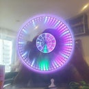
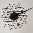
Step 4: Final Piece
Hang it on the wall using a screw (make sure you have the proper fixtures for your wall) and plug it in.
Enjoy
Step 5: Future Plans
Went through a lot of iterations of this, however, am not fully happy with this:
- Planning to design this to be a lot lighter than it is currently - will probably reduce the thickness of the fins from the current 15mm to 5/10 mm. The current motors are at the limit of their power and I can't adjust the speed too much.
- Will reduce the centerpiece so that it can be printed on smaller beds - and make the fins a little larger
- Might design the fins so that they can be interchanged - I love the way spunwheel.com has multiple different designs. Let's see how that goes
- LEDs for more bling
- Adjust the code so that there is some randomization in the movement. The random movements of the spring mechanisms are wonderful.
- Might move to an M8 screw with 608 bearings instead of the M5 and 625ZZ for more stability.
Suggestions welcome.


