

Introduction: Wave Lamp - Weather and Alerts


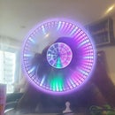

While browsing through thingiverse, I saw this absolutely amazing Wave Lamp and I HAD to build it.
https://www.thingiverse.com/thing:774456

The lamp is very well designed and prints without any supports (needs to be printed on the side)
Also, there is a lamp base that takes LED strips https://www.thingiverse.com/thing:904653

And of course, I couldn't simply leave it to be a bedside lamp. I had to make it wifi and show the weather. So, I'm using an ubiquitous ESP8266 module with WS2812B LEDs to control the colour of the lights based on today's forecast. Also, the light switches off automatically at 10:00 PM and switches ON at 6:00 AM.
Step 1: Requirements


You'll need the following items to create this wave lamp:
Tools:
- 3D printer - one that can print at least 30-35cm
- USB-TTL module to program the ESP-12E
- Hot Glue Gun
- Soldering Iron
Consumables:
- PLA - white for the lamp and another colour for the base
- 30 WS2812B Addressable RGB LEDs
- ESP8266 - 12E
- 74HCT245N
- 5V Power supply
- 5V-3.3V Power converter
- A few header pins and resistors
- Solder
Step 2: 3D Print


3D Print the following pieces
The Lamp
- Print using the white PLA rotated on the side
- Supports and Rafts are not required
- Though I did use a 5mm brim to ensure it stays stuck to the bed while printing
- I used the following settings:
- 0.8mm volcano nozzle and 0.3mm layer height.
- 2 perimeters
- 100% infill (this doesn't really matter as the pieces are so thin, they get filled in anyways)
- Be warned - this is a HUGE print and takes a lot of time. So, if you're not comfortable leaving your printer overnight (or over several nights) this is not for you. Get it printed using 3Dhubs. Mine took ~30 hours
The stand
- I modified the stand using TinkerCAD to create a cavity in the base for the electronics. You can download it here: https://www.tinkercad.com/things/aYns42p1j8Q
- Print using the coloured PLA (I used woodfill):
- 0.8mm volcano nozzle and 0.3mm layer height.
- 2 perimeters
- 20% infill
- Be warned though - the cavity I've created doesn't have any supports and the inside gets a little messy (especially with the woodfill PLA that doesn't bridge well)
The Top
This is an optional piece. I created it in TinkerCAD to hide the hole at the top of the lamp. It's nothing great, but works.
- https://www.tinkercad.com/things/5aD6V4O0jpy
- Supports and Rafts are not required
- I used the following settings:
- 0.8mm volcano nozzle and 0.3mm layer height.
- 2 perimeters
- 30% infill
Step 3: Electronic Circuit


The circuit used for this lamp is extremely simple and if your WS2812Bs (some do, some don't) work at 3.3V signal, it's even simpler as you can then avoid the 74HCT245N.
The main circuit (see schematic above):
- ESP-12E (you can skip these steps if you use one of the pre-built modules from Adafruit, Sparkfun, etc):
- Connect pins 3 and 8 to 3.3V
- Connect pins 1, 11 and 12 to 3.3V through a 10k resistor
- Connect pins 9 and 10 to GND
- Connect pin 12 to GND through an open 2-pin connector. These pins can be connected together to program the ESP-12E
- Connect pins 15 and 16 to header pins (these are RX and TX pins used to program the ESP-12E)
- 74HCT245N (ignore this if your WS2812B LEDs work directly at 3.3V)
- Connect pins 1 and 20 to +5V
- Connect pins 10 and 19 to GND
- Connect pin 2 to pin 13 of ESP-12E
- WS2812B
- Connect +5V and GND to the +5V and GND pins respectively
- Connect the DIN to pin 18 on the 74HCT245N
- If you're skipping the 74HCT245N, connect the DIN to pin 13 of the ESP-12E
Make sure all GNDs are connected together. Make sure you don't connect +5 or +3.3 to GND.
I had a couple of boards lying from an earlier project and simply used those (images above)
Step 4: Programming the ESP-12E

I used the Arduino IDE to upload the code to the ESP-12E. It needs some setup before you can do this.
Setting Up the Arduino IDE
The latest version of the Arduino IDE has made it easier to program these boards and you no longer have to go through multiple hoops to get it to work with the ESP8266 boards.
The steps are as follows:
- Download the latest IDE from https://www.arduino.cc/en/Main/Software
- Open the IDE and go to Tools -> Boards -> Boards Manager...
- Search for ESP8266 and click install (see image above)
Programming the Module
This module does not come with a USB interface, so you need to use a USB-TTL module / arduino to handle the USB communication with the computer. You can buy any one of the cheap modules available on ebay (http://www.ebay.com/sch/i.html?_from=R40&_sacat=0&...) - all work the same - only caveat being finding the correct drivers so that your computer detects the module.
The connections are pretty simple:
- Connect the GND from USB-TTL to the pin marked GND on the ESP-12E
- Connect the 3.3V from the USB-TTL to the pin marked VCC on the ESP-12E
- Connect the TX from the USB-TTL to the pin marked RX on the ESP-12E
- Connect the RX from the USB-TTL to the pin marked TX on the ESP-12E
- Short the Program header so that PIN 12 connects to GND
The module is now ready to be programmed.
Step 5: The Code
The code is heavily dependant on the tutorial on Random Nerd Tutorials https://randomnerdtutorials.com/esp8266-weather-fo... - as a matter of fact the weather bits are purely copied from there.
- Install the following libraries:
- FastLED (http://fastled.io)
- ArduinoOTA (https://github.com/esp8266/Arduino/tree/master/libraries/ArduinoOTA)
- ArduinboJSON (https://github.com/bblanchon/ArduinoJson)
- Get a OpenWeatherMap API (https://openweathermap.org/api)
- Download the code from the github: https://github.com/dushyantahuja/Wave-Lamp-with-we...
- Make the following changes:
- Wifi and Password on lines 56 and 57
- City and API Key on lines 23 and 24
- Upload to ESP-12E
If all went well, the code is uploaded, your module connects to the wifi router and shows the weather. Currently, I've set up so that:
- If it's going to cloudy / rain - Blue
- If it's going to snow / thunderstorms - Red-Blue
- If it's clear - Green
- Else Rainbow - to account for special conditions / errors
You can make changes to lines 365-377 to change these. The Palettes used are on lines 70-82
Step 6: Assemble

Assemble the following pieces:
- Wrap the LED strip to the LED stand and stick with hot glue
- Insert the circuit module at the bottom and affix with hot glue
- Slide the wave lamp on the top of the LED stand
- Place the top on the top
Plug into a 5V power supply and enjoy
Step 7: Future Plans
It's working for now, however I plan to add the following features:
- Incorporate MQTT so that it can be linked to OpenHAB
- Maybe create some kind of notification feature for missed calls / messages
- Wake up light
Suggestions welcome. And if you create one, make sure to post an image here.

Participated in the
LED Contest 2017

Participated in the
Epilog Challenge 9

Participated in the
Arduino Contest 2017


