

Introduction: 3D-printed Digital Camera Obscuras


In photography, it's usually the case that the larger the film or sensor, the better. Large-format film is a pain to deal with, but large-format sensors are extremely expensive. For example, the 6.7MP LargeSense LS45 4x5" monochrome digital back currently sells for $26,000. Fortunately, most of the properties of a large format sensor can be obtained by building a camera obscura that projects an image onto a relatively large screen, which we simply photograph using a small-sensor digital camera. Our particular obscura is of the rear projection type, which means that the obscura's lens and our digital camera are on opposite sides of the screen. In this Instructable, we'll show you how to make a 3D-printed digital camera obscura that uses your compact digital camera or cell phone to capture the image projected on a large-format screen... and can cost less than $25 to make (including the lens).
Our obscura screen uses the 4:3 aspect ratio common to most small-sensor digital cameras. Although it is 20% larger than 4x5" film, most lenses designed for that format can cover this larger area. The first figure shows how much bigger the obscura screen is compared to some common sensor sizes. The area is 10.7X that of a medium-format sensor, 18X a full-frame sensor, 224X the exceptionally-large-for-a-cell-phone sensor in the Samsung Gallaxy S20 Ultra, and 554X the sensor in a Canon PowerShot ELPH 180 compact camera.
Why do this? In some photographs, the subject is reasonably sharp, but everything behind, or in front of, the subject seems to melt away into a soft blur. That smooth out-of-focus image is known as good bokeh. To achieve it, you need a shallow depth of field (range of distances simultaneously in focus), which is the result of using a lens with a long focal length or a fast (small) f/number. Directly using a moderately fast long lens on a small-sensor camera works, but then you only get a tiny angle of view. Using a fast long lens to project on a large screen, we can get a shallow depth of field while keeping a wider angle of view. Perhaps the fastest lens ever made for a full-frame camera was the Carl Zeiss Super-Q-Gigantar 40mm f/0.33; however, some versions of the digital camera obscura here behave like even faster full-frame lenses. Just to be clear, the "Q" in the name of that Zeiss lens stands for "Quatsch," which is German for "Nonsense," and neither that Zeiss lens nor any other comparably-fast lenses produce high-quality images... including the ones used in this Instructable. Still, even the low-quality images are quite distinctive. Lenses for 4x5 cameras that can produce higher-quality images with somewhat slower apertures are common, and using, for example, a 135mm f/4.5 on this obscura makes the equivalent of a decent 32mm f/1.1 lens on a full-frame camera. The second image here shows the live view from a cell phone using a rather cheap 135mm f/2.2 lens on the obscura, for a full-frame equivalent 32mm f/0.53. Compare that to 25mm f/6.5 full-frame equivalent for directly using the native lens of an S20 Ultra or 28-224mm f/17.9-38.6 for the ELPH 180. The next two images are that scene as captured using Faboky with that lens and with a Fresnel lens (don't worry; we'll be explaining how that works).
An obscura used in this way is commonly known as a depth-of-field adapter. There have been a number of depth-of-field adapters for using full-frame lenses with cameras that have smaller sensors and fixed lenses, including ones from Ulanzi, BeastGrip, and Redrock Micro, but they use very small screens, which limits the benefit. The DIY project Perkiscope uses a very large screen to behave like a 35mm f/0.4 lens on a full-frame camera. However, Perkiscope is huge, heavy, a complex and expensive build, and requires an episcope lens that is neither cheap nor readily available. Our design's screen is just small enough to make the housing printable on most 3D printers, but the lens is the really special trick: we create a viable lens simply by trimming a cheap Fresnel sheet magnifier to size. This Fresnel lens is far from perfect, but it is a roughly 290mm f/1.63 lens that can project an image to fill our screen, and using these Fresnel lenses we can implement the full-frame equivalent of 70mm f/0.4, 35mm f/0.19, or 23mm f/0.13.
There are other reasons to use an obscura too. In April 2016, I posted my 3D-printable Camera Obscura for Canon PowerShot ELPH115IS on Thingiverse. It used a pinhole lens to produce an ultra-wide-angle view with everything in focus, essentially the opposite of the depth-of-field adapter goal. However, the construction is quite similar, and the design in this Instructable can be used for pinhole imaging as well. The most different obscura I've built is FourSee, which is a front-projection obscura used so that four separate cameras can simultaneously be sampling a scene from the exact same point of view; this Instructible will not be discussing FourSee nor other front-projection obscuras.
This project is primarily about making a very cheap obscura that could be used with almost any little camera: Faboky (fah-bow-key). What does Faboky stand for? Well, initially it wasFresnel Apodized Bokeh Obscura from KentuckY, celebrating the use of a Fresnel lens and an apodizing filter to help shape the bokeh, and I am a professor at the University of Kentucky (perhaps the wildcat photos made that a bit obvious?). Now that it also has versions using a conventional lens, with neither Fresnel nor apodizer, and can work with a wide range of cameras, perhaps Flexibly Adaptable Bokeh Obscura from KentuckY would be a more accurate expansion of the name. Then again, we also tell you how to configure it for use with a pinhole, in which case it technically never generates any bokeh because everything is equally in focus. Naming things is hard...
Fortunately, if you have a 3D printer, making Faboky is not hard. Plan on it taking more than a day to 3D-print the rather large parts, but there are minimal other materials or assembly work required. Faboky also is easy to use, and (except for the pinhole versions) even can be shot handheld. As they often measure the weight of camera equipment at DPReview TV, a typical configuration of Faboky weighs less than 1/2 of a Nikon 58mm f/0.95 Noct -- less than 1000g. Of course, any version of Faboky can create quite distinctive images, and most versions even can be used handheld!
The last three photos here should give you reasonable expectations about the image quality that Faboky can deliver with a Fresnel lens, a fast conventional 4x5" lens, or a pinhole. They are not sharp, but they are very distinctive and all three were captured using the tiny sensor in an ELPH 180 compact camera. Still want to make a Faboky? Read on...
Supplies


What does it take to build Faboky? There are some tools and some materials. To be precise, Faboky has lots of different variations (four of which are pictured here), so you'll probably want to read the whole Instructable before deciding what version you want to build and thus exactly what tools and materials you will need; the lists don't cover all versions.
The primary tools are:
- A 3D printer capable of printing an object that minimally requires a 192x192x170mm volume or a 202mm diameter cylinder 170mm tall. Those dimensions are close to the maximum allowed by most 3D printers, so make sure it will fit on yours. In fact, the Fresnel lens used in Faboky could give a wider view angle and faster effective aperture by using a significantly larger screen... it's just that then it wouldn't fit on most 3D printers.
- A laser or inkjet printer for making the optional apodization filter.
- A pair of scissors for trimming the Fresnel lens and apodization filter.
- A marker (used only for making temporary cutting marks).
The primary materials are:
- A typical version of Faboky uses significantly less than 1000g of PLA filament, but precisely how much can vary a lot based on which version, slicing parameters, and properties of your printer. For most parts, ideally, the PLA selected should be truly Black so that 2-3 extruded layers essentially block all light. Faboky's parts generally have very thin walls, so you'll either have to use a very opaque filament or plan on painting to make light-tight parts. The two spools of PLA in the fifth photo sure look black, but the sixth image here is the cell phone mount printed using the first spool of PLA and backlit by a very bright halogen bulb; although it normally looks quite black, it obviously transmits deep red and NIR unless painted (the inside looks black because it was given one coat of Black 2.0 paint).
- One to three Fresnel magnifier sheets. The ones we used, as shown in the seventh image, are Opticlens brand 7"x10.25" made of clear PVC 0.01" thick. It is advertised as providing 3X magnification. A 5-pack cost $10.99 via Amazon, so per-Fresnel-sheet cost was under $2.50.
- A sheet of screen material large enough to cover a screen opening of 5.6"x4.2". The rear-projection screen material is critical to the performance of Faboky, and it may take a few tries to find the best choice. The best I've found is a piece cut from a 3'x75' roll of HP High-gloss White Film for Inkjet C3885A, which is no longer available. It is 165 gsm 4.7 mil thick polyester, ISO brightness 90, and opacity 89%. There are apparently similar films sold in smaller cut-sheet sizes by various manufacturers (e.g., Xerox), but you only need one sheet. Thus, I recommend visiting a local arts/crafts store where you can examine the properties of various "art papers" in person before purchase. Tracing paper, rice paper, Vellum, diffusers, polyester drafting film, "milky" plastic sheets, and even cutting board mats are all possibilities. Most people think you want something that looks like ground glass, but you want a material that is thin, neutral in color, translucent (not transparent), and shows very little texture. Step 10 explains how to test potential screen materials. The eighth photo here shows Vellum and the HP white film.
- 1/4-20 screws: two at least 3/4" long and two 3" long. 3D-printed 1/4-20 screws may be substituted if desired. Although these are shown here a regular screws, the two long ones are more convenient as thumb screws, but it can be hard to find ones 3" long. It also can be more convenient to use the two shorter screws with wing nuts, although no nuts are required. Adding to the confusion here, I've included 3D printable designs for 1/2" screws and a wing-nut-like thumbscrew for the versions using a conventional lens; they work fine for that application, but they are touchy to print and are not as strong as metal screws.
- The optional apodization filter can be 3D printed, or a better-quality version can be made using a sheet of clear overhead transparency material that is compatible with your laser or inkjet printer.
- Tape, glue, or some other mechanism for holding the screen, Fresnel lens and apodizer, or pinhole in place.
- Optionally, some paints and painting supplies.
You also will need a digital camera to use Faboky. Although you could design and build your own, there currently are two camera mount options. You can use either:
- A compact camera similar to a Canon PowerShot ELPH 180. There are many Canon PowerShot models that can use the same mount, including many ELPH models, and it is common that various choices will be available used on eBay for less than $30. Camera resolution is not critical. I suggest preferring models that are supported by the free CHDK software, as that can provide raw capture and other useful features. If you are considering a very different camera, I strongly recommend comparing lens dimensions and position by looking at CameraSize.Com and comparing with an ELPH 180; for example, that tool makes it pretty obvious that a Canon PowerShot SX530 HS would NOT be compatible whereas a Canon PowerShot ELPH 115 IS probably is. Of course, you could modify the elphback discussed in Step 13 to make it compatible with various other cameras, and alternative versions may be posted later...
- A smartphone camera. I tested with the Samsung Galaxy S20 ultra using the normal lens, but the mount is very adaptable to cell phone size and camera lens position on the phone. Just make sure your cell phone is held safely and securely, because I accept no responsibility for anything bad that might happen to your cell phone.
Stock Configurations
Picking parts is pretty complex because of all the options, so here are a few "stock" configuration suggestions:
- Single-element Fresnel version for a cell phone: you need a screen, 7"x10.25" Fresnel magnifier, two 1/4-20 1/2" screws, two 1/4-20 3" screws, and must 3D print faboky220912cliphood.stl, faboky220912front200.stl, faboky220912middle210.stl, faboky220912seam.stl, faboky220912back.stl, faboky220912topclamp.stl, and faboky220912bottomclamp.stl
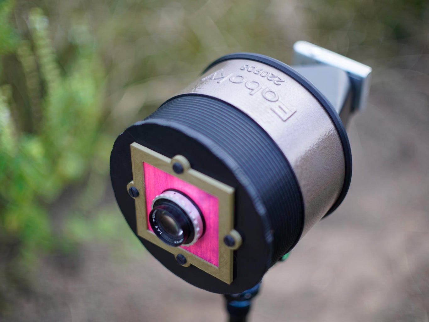
- Version using a 135mm conventional 4x5" lens for a cell phone: you need a screen, two 1/4-20 1/2" screws, two 1/4-20 3" screws, and must 3D print four of faboky220912thumbscrew.stl, faboky220912lensholder.stl, faboky220912front4x4100.stl, faboky220912middle110.stl, faboky220912seam.stl, faboky220912back.stl, faboky220912topclamp.stl, and faboky220912bottomclamp.stl
- Version using a pinhole for a Canon PowerShot ELPH 180: you need a screen, two 1/4-20 1/2" screws, and must 3D print faboky220912frontpin100.stl, faboky220912middle110.stl, faboky220912seam.stl, faboky220912elphback.stl, and faboky220912thumbscrew.stl,
Step 1: The Fresnel Lens


Got the 7"x10.25" Fresnel magnifier? Good. We're not going to do anything with it in this step except hopefully help you to understand how it works and how we will be using it. You can skip the rest of this step if you don't care to know... and you can skip to Step 3 if you'll instead be using a conventional 4x5 lens, or skip to Step 4 if you'll be using a pinhole lens.
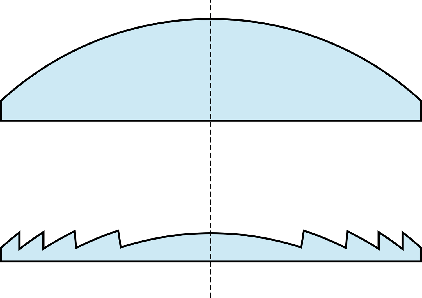
A Fresnel lens (as shown in the diagram copied from the Wikipedia page) is basically a sneaky way to make a conventional lens less thick. Light is only bent by a lens when it strikes a change in the refractive index -- in other words, all that glass inside a lens element doesn't really matter much; the bending happens as the light hits the surface at whatever angle. Thus, by logically cutting a plano-convex lens (flat on one side, convex on the other) into many concentric circles and removing nearly all the thickness of each slice while preserving the surface angles, we get an equivalent very thin lens. Our Fresnel is so lightweight because it is made from PVC plastic, instead of glass, and is only 0.01" thick. A comparable conventional lens made of glass would probably weigh several pounds, while our Fresnel weighs less than 16g!
Our 7"x10.25" Fresnel magnifier lens has a focal length that measures about 290mm. It's the ratio of lens aperture area to focal length that determines how bright the image formed will be. Unmodified, this magnifier is approximately an f/1.2 lens -- a very bright, fast, lens. However, the goal for Faboky is making prettier bokeh, not letting more light through. So, how does using this lens in the Faboky camera obscura achieve our goal?
The desirable blur in bokeh is caused by each point of light in the scene that is out of focus being rendered not as a point, but spread over a larger region. The projected image of a single point of light is called the point spread function (PSF), and if the point is out-of-focus (OOF) we'll call it the OOF PSF. The bokeh produced by a lens is simply the result of imaging every OOF point in the scene as its OOF PSF. So, let's talk about three key properties of OOF PSF:
- How big is each OOF PSF? The more OOF the point is, the bigger the area that light from that point will be spread over. Put another way, to enlarge the OOF PSF, we want to reduce the depth of field. Having your subject very close to the camera helps make the background more OOF. However, some lenses, such as those on cell phones and compact cameras, never let the OOF PSF get very big. In general, the larger the diameter of the lens is, the bigger the OOF PSF. Our Fresnel lens makes very large OOF PSF.
- What is the shape of the OOF PSF? The overall shape of the OOF PSF of a lens matches the shape of the lens aperture, so a lens with a circular aperture will produce OOF PSF shaped like circular discs, which look more natural than other shapes, such as the pentagonal shape you would get from a lens with 5 aperture blades. If we were to use the full 7"x10.25" sheet magnifier as our lens, the OOF PSF would be rectangular, which isn't a good look. Thus, we'll be cutting and masking it to make a perfectly circular aperture -- which will reduce the brightness of the lens to approximately f/1.57.
- How is the light distributed over the OOF PSF? In theory, a perfect lens would spread the light perfectly evenly over the shape of the OOF PSF, as seen in the second figure in this step, which is the actual OOF PSF of one of my well-corrected "fast fifty" full-frame lenses (a 55mm f/1.8). The catch is that's not really what we want, because that would leave a very sharp edge on the OOF PSF. For example, a bright line in the scene would be rendered as a thicker bright line with sharp edges rather than a softly blurring edge; this defect is known as nisen bokeh, or broken, bad, nervous, or distracting bokeh. To avoid nisen bokeh, we want the OOF PSF to gradually get darker as we near the edge. There are several ways to accomplish this, but the Fresnel lens used in Faboky naturally has a lot of uncorrected spherical aberration (SA), and that makes the energy smoothly dissipate toward the edges of the OOF PSF. The third figure is the image of a single OOF point of light through Faboky's circular-aperture Fresnel. The result is extremely smooth bokeh, but having the edges of the OOF PSF so dim effectively decreases the perceived size of the OOF PSF, making things look less OOF than they really are.
- How is vignetting handled? The red area in the fourth figure shows how the shape of a typical lens OOF PSF is deformed by internal vignetting off axis. You'll often hear people describe this effect as "cat's eye" bokeh. This vignetting comes from the fact that most lenses have multiple elements resulting in very significant thiickness for the lens overall, with some internal components blocking some off-axis light rays. The good news is that a Fresnel lens is very thin, so there really isn't anything to cause this type of vignetting and the shape of OOF PSF does not change very much off axis.
Summing up all that, our Fresnel lens is really a great choice for making pretty bokeh. The biggest problem is that it is arguably making the bokeh too smooth, but that's what Step 2 is about...
One more note: it's relatively hard to find Fresnel magnifier sheets with various different focal lengths. However, each Fresnel magnifier is a plano-convex element, and simply stacking multiple Fresnels effectively divides the focal length. Stacking two will give approximately half the focal length and stacking three will give about one third -- all without changing the diameter of the aperture, thus making the lens also have a correspondingly smaller f/number. There will be some misalignment, and stacking Fresnels does degrade the image quality more than using a single Fresnel, but the shorter focal length can be more desirable.
How do we get this lens on a camera that does not have interchangeable lenses? Well, that's where the rear-projection obscura comes in. All that we need to do is to make a dark chamber with the Fresnel lens on one end and a rear-projection screen on the other. Of course, to be able to focus the lens, we need to be able to adjust the length of that chamber. Our digital camera mounts on the other side of the screen at the end of another dark chamber. It does not need to change focus; it is always photographing the screen a fixed distance straight ahead of it.
The other important aspect of using an obscura is that our 290mm f/1.6 lens does not deliver particularly high resolution in terms of line pairs resolved per mm. It's incredibly difficult, if not impossible, to build a lens this fast to resolve fine detail, and the lens we're using isn't a fancy design. However, over the area of a relatively large screen (7" diagonal), you get a reasonable number of line pairs resolved, and photographing that screen basically preserves that total resolution. The images have very low contrast and you'll be disappointed if you're expecting really high sharpness, but you can get effective total resolution in the megapixel range from Faboky with a Fresnel lens.
Step 2: Apodizing Filters


The word apodization refers to any modification of the shape of a mathematical function -- in the case of a lens, the mathematical function we are modifying is the energy distribution within the OOF PSF.
As described in Step 1, a well-corrected lens generally produces an OOF PSF that is an evenly-shaded disc with a sharp edge. By applying an apodizing filter that is darker at the edges, such as the first pattern shown here, the OOF PSF can be made to have softer edges and produce smoother bokeh.
In Step 1 we pointed-out that our Fresnel lens naturally has a lot of undercorrected spherical aberration that makes the OOF PSF quickly darken towards the edges. Well, it turns out that can be altered by apodization too. An apodizing filter that is darker in the middle and smoothly brightening towards the edges, such as the second image here, can convert the Fresnel lens OOF PSF into one that is much closer to being an evenly shaded disc. Think of it as approximating the inverse of the pattern in the third figure of Step 1.
So, if what you'd really like is big bokeh with somewhat more distinct edges, an apodized Fresnel can do that. The projected image will be darker due to the apodizing filter blocking much of the light, but we still get to use our cheap, readily available, lightweight, Fresnel lens while having good control over the OOF PSF. Of course, if you like the images without an apodizer, there's nothing wrong with not using an apodizing filter and you can skip to Step 5. After experimenting with using various darker-in-the-middle apodizers with the Fresnel lenses, I felt it usually wasn't worthwhile; it's basically going out of our way to make the bokeh look bigger at the expense of being less smooth.
So, how do we make an apodizing filter for the Fresnel lens?
It turns out that making good apodizing filters is generally very difficult. While it seems simple enough to make a filter with the appropriate density gradation, any unevenness in the shading can create interference patterns that make the OOF PSF look grainy rather than smooth. The most artifact-free apodizing filters are made by creating a shaped lens element out of smoked glass, as was done in the STF (smooth trans focus) lenses: Minolta/Sony 135mm F2.8 [T4.5] STF, Sony FE 100mm F2.8 STF GM OSS, and Laowa 105mm f/2 STF. Some other lenses, such as the Fujifilm XF 56mm F1.2 R APD, instead use a flat gradient filter that is probably made by sputtering. I've made my own apodizing filters using (in order of decreasing quality): B&W non-dye-based negative film (e.g., Ilford Pan F Plus used like Markus Keinath did), a homemade spray-paint sputtering machine, laser or inkjet printing on transparency material, and even an Imagon-like "sink strainer" design made with a programmable paper cutter, laser cutter, or 3D printer. All work, but bokeh become increasingly textured with coarser apodizers...
The easiest to make apodizer is the spiral "sink strainer" design that you can 3D print, as shown in the third figure. Overall, it is a pretty bad approximation to the smooth shading we want, and in the fifth figure you can see the measured full color result. It does produce a more even distribution of energy across the full OOF PSF, but with an obvious texture. The hole pattern is perhaps not as obvious as one might expect, but the combination of aberrations from the Fresnel lens and diffraction effects produces a smeary spiral pattern with little rainbow effects. Yuck.
A higher-quality apodizer results from inkjet or laser printing on overhead transparency material. Using this method, bokeh texturing is not much of a problem with our 7" diameter Fresnel lens projecting a 180mm diameter image. Both those numbers are large enough that the diffraction effects from the granularity of laser or inkjet printing are negligible. So, take a sheet of overhead transparency material and laser or inkjet print the apodizing pattern on it so that the pattern is 7" in diameter. That's it. Just be careful that the transparency material you use is intended for your type of printer: inkjet inks generally will not stick to laser transparency material, and some inkjet transparency material can partially melt inside a laser printer. If the apodization is not strong enough because your printer's blacks are somewhat transparent, you could print on both sides of the transparency or stack two or more printed apodizers, but more layers of filter do tend to reduce image contrast significantly. Be warned that most overhead transparency material isn't perfectly clear, and even one will act in part as a diffuser, lowering contrast.
The last three images here (all at the same scale as the native OOF PSF image in Step 1) show how the OOF PSF can be modified using a dark-center apodizer; first with a weak apodizer, then with one about twice as strong, and finally with one about four times as strong. The last OOF PSF is clearly over-apodized, with a bright edge and dark center starting to be evident -- and that would result in nisen bokeh. However, the other two OOF PSFs show that the apparent size of the OOF PSF can be increased without completely sacrificing the smoothing effect of darker edges on the bokeh. I consider the first two levels of apodization here to be viable apodizing patterns for the Fresnel lens, but you can easily make your own stronger or weaker filter pattern by adjusting the levels of the image using an image editing program like gimp.
Where does the apodizing filter go?
The other tricky issue for apodizing filters, in general, is that they will act as vignetting elements, darkening the edges of the whole image rather than the OOF PSF, if put in the wrong place. For most lenses, there are several viable places to put the apodizing filter. The placement most people consider ideal is where the lens aperture iris is, but our Fresnel lens doesn't have any iris. For most lenses, immediately in front of the first element or behind the last element are both viable positions and both of those work for our Fresnel lens. For Faboky, we'll simply be sandwiching the apodizing filter immediately in front of the Fresnel lens with the printed side facing the Fresnel element.In this way, both the Fresnel element and the printing are somewhat protected.
Continue reading with Step 5.
Step 3: Using a Conventional 4x5" Camera Lens


This step is about using a conventional 4x5" camera lens instead of a Fresnel.
Lens coverage: Conventional large-format lenses come in a wide range of sizes, shapes, and mounts. The coverage of a lens is the diameter of the reasonably sharp image circle it projects at infinity focus. The active area of a 4x5" sheet of film is approximately 121x97mm, which means the diagonal is sqrt(121^2+97^2) = 155mm. However, many large-format cameras allow tilt and shift movements, so a lens might need to have a bit larger coverage circle to still cover that diagonal when the lens is titled or shifted somewhat off center. Faboky does not (yet) allow tilt nor shift of the lens, but the screen is larger than standard 4x5", at 144x108mm with a diagonal of 180mm. So, how do you know if a particular large-format lens will cover that 180mm diagonal?
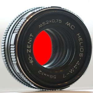
Not surprisingly, the best way to know is to test and measure it yourself. You cannot know this just by looking at the lens; there are plenty of large lenses with tiny coverage and tiny lenses with large coverage. There are some online resources that can help. Michael K. Davis has assembled lists of coverage of various current-production large-format lenses and Michael Gudzinowicz has assembled a list for discontinued lenses, but don't be surprised if that random lens you saw on eBay isn't in any of those lists. For example, one might expect the Schneider Tele-Arton 250mm f/5.6 to cover at least 5x7" film, but in fact it only reaches 158mm when stopped down to f/22, which means it would almost certainly leave dark corners on Faboky's screen. In contrast, a Nikkor W 135mm f/5.6 covers 200mm. As a rule of thumb, you can expect that most large-format lenses of about 135mm or longer focal length will cover 4x5" and at least be close to covering Faboky's screen. This is especially true of lenses made for enlargers, which can be particularly good bargains as large-format lenses. For example, the tiny Wollensak Enlarging Raptar 135mm f/4.5 shown in the third image can cover 4x5" with a good quality image despite often selling for under $30 used.
Lens focal length and aperture: The "crop factor" for full-frame relative to Faboky's screen is approximately 4.16. Thus, a 135mm f/4.5 will become the equivalent of a 135/4.16 = 32.5mm with an f/number of 4.5/4.16 = 1.08. If you want a particular view angle and equivalent aperture, that's how you should pick your lens. For example, if you want something around the equivalent of a 50mm f/0.75, you should be looking for a lens close to 208mm f/3.2.
You also should be aware that the lens focal length is usually pretty close to the distance needed between the screen and middle of the lens when focus is set for infinity. Thus, a 208mm lens usually implies that the Faboky chamber between the lens and screen will need to be at least about 200mm long. Of course, you should test and measure the precise distance needed for infinity focus so you'll know how long to make the middle section of Faboky. To focus closer, the focusing front part of the tube must be able to extend significantly, and again the best way to determine how long the front should be is to test and measure for your desired minimum focus distance. Both the infinity-focus middle length and front extension length generally will need to be longer for longer focal length lenses. In other words, Faboky for a 135mm lens can be much smaller, and quicker to 3D print, than Faboky for a 208mm lens.
Choice of lens mount: Unfortunately, lens mounts for large-format lenses are very poorly standardized -- or perhaps I should say there are way too many standards. For Faboky, we have gone with a mount that is very common among 4x5" cameras, and was used by such companies as Graflex and Burke & James: 4x4" square lensboards. Some years ago, I wrote the Instructible Custom Lensboards for a Large-Format Camera telling people how to make their own 4x4" lensboards out of thin wood, but it's even easier now to 3D print them.
How does your lens attach to the lensboard? Well, some lenses come in shutter mounts that have front and back parts that screw-in trapping the lensboard between. Those are fine as long as the shutter has a "T" option. The "T" shutter speed means timed exposure in which you release the shutter once to open and a second time to close. You need this because for Faboky you really want the shutter open all the time. It is also quite common that an enlarger lens or barrel lens will have no shutter, but will come with a screw-threaded retaining ring so that you push the lens through the lensboard and then lock it in place by screwing-in the retaining ring from behind. In any case, the lensboard is not part of Faboky; Faboky simply includes a mounting plate with four screws for mounting a 4x4" lensboard.
Once you have picked a lens and mounted it in a 4x4" lensboard, go to Step 5.
Step 4: Using a Pinhole


This step is about using a pinhole "lens" instead of a Fresnel or conventional lens.
A pinhole is by far the simplest type of lens, although it is also quite versatile. The versatility comes from the fact that changing the distance between the pinhole and screen does not change the focus distance; all distances are always roughly in focus, which is the same as saying depth of field is infinite. Instead, changing the distance between the pinhole and screen effectively changes the focal length of the pinhole. Thus, any pinhole is potentially a zoom lens.
Unlike the other lenses discussed in this Instructable, what pinhole lenses do is not as distinctively different from what you can get directly using a camera with a small sensor: they naturally have lots of depth of field. Personally, I don't find pinholes all that compelling. However, they do produce perfectly rectilinear images even at very short focal lengths, which is why I made my 3D-printable Camera Obscura for Canon PowerShot ELPH115IS back in 2016. Thus, I'd suggest making either that older pinhole camera obscura or a very short Faboky if you want to use a pinhole, although longer focal lengths work too. I'd also suggest that using a heavily textured screen can be an advantage for a pinhole obscura, adding significantly to how distinctive the captured images are.
How big should the pinhole be? There is a formula for computing the optimal diameter of the pinhole:
diameter = constant * sqrt(focal_length * wavelength)
There were various constant values proposed, but sqrt(2.44) = 1.56 is the ideal value as computed based on Fraunhofer diffraction. Typically, the wavelength used is 550nm = 0.00055mm (yellow-green), which allows simplifying the formula to diameter = 0.0366 * sqrt(focal_length). For example, a 135mm pinhole would have an ideal diameter of 0.425mm, and would result in the field of view of a 32.5mm full-frame lens. However, the aperture of that 135mm lens would be a very dim f/317, and that would still be f/76 for the full-frame equivalent -- a very dark lens with infinite depth of field.
Given the additional reduction in brightness from the screen, the result is that exposure times will be very long even in bright daylight. This is part of why we like the Canon PowerShots under CHDK: with CHDK, you can set absurdly long exposure times; for example, with very bright interior lighting, it took an exposure of 3 minutes at ISO 800 to capture the first image through that f/317 pinhole. The unfortunate corollary is that even the slightest light leak in Faboky's construction will become quite visible. For this reason, it is strongly recommended that 3D-printed parts of any pinhole Faboky that might light leak be given several coats of opaque paint. It may also be wise to select a screen material that is relatively bright; light will fall-off off axis, but that is more easily dealt with than having insufficient light for the digital camera's exposure system to work correctly.
Construction of the pinhole: Although 0.42mm is a hole size that could theoretically be 3D-printed, I strongly discourage that because precision of the pinhole makes a significant difference in image quality.
The pinhole can be made in any of many possible ways. I tested using aluminum duct tape with a literal pinhole, but the hole produced was sloppy. The best alternative was to cut apart an aluminum soda can to get a piece of thin aluminum (which is still much more solid than the duct tape), as shown in the second image. Be careful -- the cut aluminum will have very sharp edges! The third image shows the result of drilling several roughly 0.4mm holes for the pinhole: it produced a nicely circular hole with a clean edge. I then sanded both sides of the aluminum scrap to completely remove any coatings and further ensure the pinhole edge was clean. Finally, I used a Q-tip to brush Aluminum Black on the pinhole metal, producing a good approximation to a matte-black anodized finish as shown in the last image. However, leaving the aluminum bare is unlikely to cause any problems. I used blue painter's tape to tape it into position from the inside of the frontpin part (as described in Step 8).
Alternatively, laser-drilled pinholes of various sizes are commercially available for about $10. Typically, these are mounted in steel discs ranging from 0.5" to 1.5" in diameter and also can be mounted in Faboky using tape or glue.
Step 5: The 3D Printed Parts, an Overview

All the parts for the initial release version, Faboky 220912, are posted on Thingiverse as Thing 5502361... which Thingiverse doesn't seem to be correctly indexing. Thus, it is also posted at Printables.
The 3D printing is not going to go fast. Although all the 3D-printed parts for a typical Faboky don't even use 1Kg of filament, it is probably the biggest volume object you've ever printed. Total print time using 0.3mm layer height and 20% infill was about 24 hours on an Anycubic Linear Plus, and could easily be a week with a slower printer and poor choice of slicing parameters. Although the default parameters are set reasonably, the design is fully parametric, and there are a lot of options. For example, an opaque black PLA filament can be used for all parts, but constraints on color choices are noted for each part.
Before you start printing anything, let's walk through a little description of the major 3D-printed parts, starting with the components that are used for all versions of Faboky:
- Front, Front4x4, or Frontpin: this is the front half of the focusing thread and also provides the lens mount. There are three different versions: front for the Fresnel lens, front4x4 for the conventional lensboard, and frontpin for a pinhole lens. It takes a lot of turns of the focusing thread to significantly change the focus distance, but that's by design; it makes for more accurate focusing and keeps the focus from slipping. The thread uses a 4mm pitch with an easy-to-print 45-degree angle rather than the 30-degree metric standard. The walls of this part are very thin, but are always thick enough for at least 2-3 extruded strands. This makes it a bit fiddly to get the thread started when mating the front and middle pieces because the thread can easily be temporarily deformed a bit if you apply too much pressure, but the thin walls dramatically reduce weight and print time... and this part will take a long time to print even with the thin walls. Although this part could be made in any color, it is critical that it not leak light, so prefer opaque black. Even most black filaments are not fully opaque, especially in the near infrared (near infrared leaks tend to show as slight reddish casts in images); if your filament isn't opaque enough, the flat interior of the front part can be painted with something like Black 2.0 (which I have found to be excellent for killing reflections and light-sealing PLA printed parts).
- Middle: this is the back half of the focusing thread and also provides the surface and mask for the screen and an Arca Swiss compatible tripod mount. The Arca mount is large enough so that load is distributed over a reasonable area when it is clamped on a tripod. Faboky does have a 3D-printed 1/4-20 tripod thread in the Arca mount, but although Faboky isn't heavy, it's long enough that bumping into Faboky easily could have enough leverage to destroy such a thread. Like the front, this middle is a big part that will take a long time to print and must be light tight. Not only are the walls quite thin, but only the very front portion of the middle is threaded because that saves material, speeding-up print time and reducing weight. The flat inside walls can be painted like the inside of the front part, and it also is possible to paint the outside of the cylinder. For example, a very nice finish can be obtained by using masking tape to keep paint off the ends of the tube and the Arca mount and then spray painting the outside of the tube with a textured paint, such as any of the spray paints that give a hammered metal look -- they can very effectively hide the usual 3D-printed texture.
- Back or ELPHBack: this is the part that allows mounting either a cell phone (back) or a compact camera similar to the Canon PowerShot ELPH 180 (elphback).
- Seam: this part is an (optional) cover for the join between the middle and either type of back. I didn't find it to be necessary with either the Fresnel or 4x5" camera lenses, but the very dark pinholes otherwise showed some light leaking in the tiny gap between the middle and back where the screen is sandwiched. This part, which simply blocks the direct light path, prints fairly quickly.
These pieces require a 3D printer with a fairly large build volume, but will fit (barely) on most commodity FDM printers.
There are a large number of different length versions of the front, front4x4, frontpin, and middle parts for you to choose from because you want to pick lengths that give infinity focus, a reasonable close focus, and still fit in your printer's build volume. Remember that lens focal lengths are often not marked or measured with great accuracy, and making the minimum combined length for the front and middle too long will make it impossible to focus to infinity. Guidelines for picking the appropriate lengths are given in the steps describing the different options.
Keep in mind that many parts are somewhat interchangeable between Faboky versions, so you might want to pick compromise lengths that allow more reuse. For example, if you expect to be using both the 290mm single-element Fresnel lens and a 150mm conventional lens, you might make the middle 125mm and use it with both a 275mm front and a 125mm front4x4. Thus, you might want to browse all potentially relevant sections of this Instructable before starting those big, long, 3D prints...
The first set of options has to do with choice of lens. Go to Step 6 for Fresnel lens, Step 7 for conventional 4x5" camera lenses, and Step 8 for pinholes.
Step 6: Parts for Using Fresnel Lenses


So, what parts do you need for using a Fresnel lens?
To begin with, you will need a front and a middle. The question is, how big should they be?
- If you are using a 290mm single-element Fresnel lens, the middle should probably be about 285mm and the front should be no longer than 275mm to be able to be fully retracted. Many 3D printers cannot print objects that tall, so you might need to make both shorter, but that's not a big problem as long as the lengths of the front plus middle sum to more than about 325mm. Shorter sums will not be able to focus as close.
- If you are using a 145mm two-element stack of Fresnel lenses, the middle should be about 135mm long and the front should be between 75mm and 125mm long.
- If you are using a 97mm three-element stack of Fresnel lenses, the middle should be about 85mm long and the front should be between 50mm and 75mm long.
In addition, you will need a hood or cliphood; I recommend the cliphood, although the hood looks nicer if you don't care about being able to disassemble the Fresnel lens after assembly. This is the trim piece that will hold the apodization filter and Fresnel lens in place. The cliphood clips on/off; the hood gets either glued or welded in place. Basically, you take the trimmed Fresnel lens(es), align them as best you can with the 7" diameter opening in the front, and tape or glue the edges to the flat edge to hold them in place. If you are using an apodizer, it gets centered on top of that. Then you use the hood or cliphood to clamp that stack in place.
The hood or cliphood also acts as a tiny bit of a hood against lens flare (hence the name), but it is too shallow to make much difference in that respect. However, it also serves as a nice set-back to protect the apodization filter and Fresnel lens -- I didn't bother with making a lenscap. The color of this part is not critical, although highly reflective colors might increase lens flare.
To put together the lens assembly, which is made from the 3D-printed hood and front, the Fresnel lens, and (optionally) your apodization filter printed on transparency material:
- Start by taking the front and centering it forward-side-down (the same orientation it is printed in) on the Fresnel lens set on a table with the shiny (flat) side up. This will serve as your guide for cutting the Fresnel lens to size. It's probably easiest to use a marker to trace the outside of the front on the Fresnel sheet and then separately cut it down to fit that size. To be precise, you want the Fresnel lens to be cut slightly smaller than the front but also slightly larger than 7" across... everywhere except where the Fresnel sheet was already 7" across. It should look like the cut Fresnels in the first photo here.
- If you are using an apodizing filter, perform the same trace and cut sequence on it so that you end up with a slightly larger than 7" apodizing filter centered in a slightly larger circle of transparency material.
- Carefully place the Fresnel lens with the shiny side against the 3D-printed front and use a few small pieces of tape to tack it in position. Make sure that the lens is centered and supported by (or at least touching) the edge of the Front all around; it also should be laying quite flat. The second photo shows what this looks like for three Fresnel lenses stacked.
- If you are using an apodizing filter, place it centered on top of the Fresnel lens with the printed side towards the Fresnel. Use tape to tack it into place.
- The 3D-printed hood or cliphood is really designed to hold the lens sandwich flatly in place on the front. Slip the hood or cliphood over the lens sandwich. The cliphood should slip firmly into place, resulting in what you see in the third photo. If using the hood, although tape can hold things together for testing, a few dabs of hot glue (or using a soldering iron to spot weld) the back edge of the hood to the edge of the front will hold it more securely, and the tape then can be removed. If the apodizer or Fresnel need to be replaced later, hot glue can be peeled off and spot welds can be broken with a thin knife, so access is still possible... just not as easy as with the cliphood. The last three photos show what the three-element cliphood and one-element hood versions look like.
Next, go to Step 9 to assemble the screen.
Step 7: Parts for Using Conventional Lenses


So, what parts do you need for using a conventional lens that is already mounted in a 4x4" lensboard?
To begin with, you will need a front4x4 and a middle. The question is, how big should they be?
- If you are using a conventional lens that has a rear focus distance of F at infinity (typically, with a focal length also approximately F), the middle should be just a little shorter than F. The front4x4 should be no shorter than F+30mm minus the length of the middle, and no longer than F-10mm. For example, for a lens with F=135mm, one might make each of the middle and front4x4 135mm, but that's risking missing infinity focus if you were a little off measuring F, so 100mm would be a safer choice. Similarly, for an F=208mm lens, the middle and front4x4 might be 185mm and 175mm.
In addition, you will need:
- One (1) lensholder: this part is a simple frame to fit over the 4x4" lensboard to hold it in place, as shown in the first photo. The lensboard will be held against the front4x4 in a way that forms a light trap, so the opacity of the lensholder is not critical, and you can 3D print it using any color filament desired. I am partial to metallic-look PLA filaments for this.
- Four (4) screws: these are 3D-printable 1/4-20 screws that are used to secure the lensholder to the front4x4. They are screwed-in from the front, sandwiching the lensboard between the lensholder to the front4x4. Alternatively, you may substitute 3D-printed thumbscrews or conventional 1/4-20 screws with wing nuts. If you use conventional screws, I would recommend using four (4) 1/4-20 screws at least 1/2" long and screw them in from the inside, rather than the outside, so that four (4) 1/4-20 wing nuts can be used to secure the lensholder. That's what you see in the fourth photo.
Next, go to Step 9 to assemble the screen.
Step 8: Parts for Using a Pinhole


So, what parts do you need for using a pinhole?
To begin with, you will need a frontpin and a middle. The question is, how big should they be?
- If you are using a pinhole lens, the lengths of the middle and frontpin parts will determine the focal length zoom range. The minimum will be approximately the minimum of middle and frontpin lengths plus about 10mm. The maximum will be about 30mm less than the sum of the lengths because you want to have about 30mm of the thread between the middle and frontpin parts engaged. For example, if the middle and frontpin are 60mm and 50mm, your pinhole would be able to zoom from approximately 60mm to 90mm, and the optimal pinhole size would be between 0.28mm and 0.35mm, giving an aperture between f/212 and f/256; the resulting view angles would be like a distortion-free 14-22mm zoom on a full-frame camera.
The pinhole is mounted in the inside of the frontpin part (to offer some protection) with the pinhole centered. It can be either glued or taped in place. It is taped in the first photo and the second photo shows how the completed pinhole Faboky looks.
Next, go to Step 9 to assemble the screen.
Step 9: Projection Screen Assembly

There really isn't much assembly to do mount the projection screen on the 3D-printed Middle, but you haven't made the screen yet, have you? Here's what you need to do:
- Take a piece of your screen material and cut it to be a rectangle just slightly larger than the rectangular cut-out in the 3D-printed middle.
- If your screen material is relatively thin, position it over the back of the middle (the side that was on the printer bed), and use a couple of pieces of tape to tack it in position over the rectangular cut-out. Thin screen material is clamped between the middle and back or elphback parts when everything has been assembled. If your screen material is thick, for example, if you used a ground glass or hard plastic, the trimmed screen material is instead placed on the inside of the middle part in the flat area provided and then locked in place using hot glue.
Step 10: Assemble and Test the Obscura


The Fresnel/conventional/pinhole front and middle screen assemblies screw together in the obvious way to make an obscura. The screw thread is somewhat unusual, having a 45-degree slope and four thread starts per rotation, but this makes it easy to print and allows focusing to be reasonably fast in terms of the number of turns needed to change focus. That obscura can be tested without needing a camera attached. Here's what you must do:
- Because the walls are so thin, it is easy for the parts to deform slightly and refuse to screw together; be patient and gentle rotating the front lens assembly while holding the middle projection screen assembly and eventually you will find the thread starts with very little friction. Because both parts of the thread are printed from similar materials, there is a slight tendency for the thread to bind. If this happens, back the two pieces apart and either lightly sand or lubricate the thread before trying again.
- Of course, a pinhole image is always in focus, but with a lens focus matters. When you start threading, the focus will be fairly close, but Infinity focus will be reached when the distance between the lens and screen is roughly equal to the lens focal length. The only reason to screw-in so that the assembly is shorter than the infinity focus distance is to make Faboky smaller for easier carrying; nothing would be in focus.
Now it is time to test the obscura. Realistically, you're not really testing the obscura as much as you are testing the quality of your rear-projection screen material:
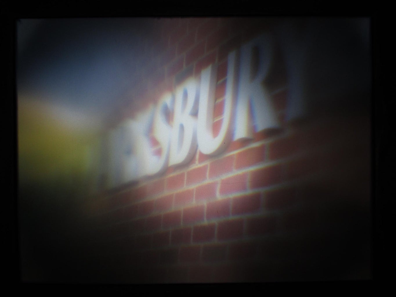
- Point the obscura at something bright and contrasty and adjust the focus by looking at the image on the rear-projection screen. Note that the image will be upside down -- that's just how lenses work. Hopefully, you see something like the photo here.
- If you see an obvious bright spot in the middle of the screen with darker corners, your screen material is not sufficiently dense to act as a focal plane and lots of the light is passing straight through. This happens mostly with ground glass or thin plastic diffuser materials. It is the same problem that, for example, makes it difficult to manually focus a lens looking through the optical viewfinder of a Canon DSLR, and they do that because an appropriate level of diffusion will make the image much dimmer. If the bright spot is extreme, go back to Step 9 and replace the screen with a different material -- however, in Step 15 we'll discuss how a bright spot can be nearly eliminated using a clever capture sequence and a little post-processing.
- Some screen materials are sufficiently diffuse, but have variations in their transmissivity due to internal structural variations in the material, such as placement of opaque fibers. If you see an excessive textural pattern, you have two options. The first is go back to Step 9 and try a different screen material. The other option is to capture a reference image of the texture and essentially subtract it out in postprocessing. Unlike the bright central spot, some people actually like the textural patterns, thinking of them much as many people view film grain: a natural artifact that suggests something about the process used for capture and can be used to artistic benefit.
If the screen material is to your liking, it's now time to mount a digital camera. As shown in the last three photos here, the cell phone and compact camera mounts can be swapped and are very similar, and they can use the same seam part, but each is significantly specialized for the type of digital camera it is intended to mount. If you want to use a cell phone, go to Step 11; to use a compact camera like the Canon PowerShot ELPH 180, go to step 13.
Step 11: Parts for Using a Cell Phone


Now that you've built the stuff that goes in front of the screen, it's time to build the stuff that goes behind it: a mount for a digital camera to photograph the screen.
Using a cell phone camera is a bit tricky in that cell phones vary in shape a lot and have a wide array of different types of cameras. The current design was tested for the main camera of a Samsung S20 Ultra, but should work for many other cell phone cameras. There are three potential fit problems:
- The distance to the screen is set so the S20 Ultra captures a bit more than the complete screen in 4:3 aspect mode. Other cell phone cameras might capture a somewhat wider or narrower view, potentially failing to capture the complete screen. It also can be a bit harder for the cell phone to focus because if the Faboky lens isn't in focus, the edges of the screen would be the only sharp content for the cell phone to focus on. We might make back that allows adjusting this distance in the future... but not yet.
- Generally, Faboky expects your cell phone's back to be against the Faboky back port -- which can be problematic if there is very non-flat stuff on the back of your phone, such as various types of add-on cell phone grips. That said, keeping your cell phone in a simple case while mounted is probably not a problem.
- Although the clamping arrangement shown in the first photo is very adjustable, it is entirely up to the user to secure their phone in a way that will ensure it does not get damaged. Don't over-tighten things, but make sure that your phone isn't going to fall out of the mount. If you have any doubts, consider using some additional methods to secure your cell phone, perhaps even making some kind of safety strap to ensure that if your cell phone falls, it doesn't fall too far. You might also want to use some padding to ensure that the clamping system cannot scratch your phone. By building Faboky, you agree that safety of your cell phone is entirely your responsibility.
In sum, if there are any potential fit issues, don't risk your cell phone, and consider modifying the design of the 3D-printed parts to better mate with your phone.
The parts needed for the cell phone adjustable clamping mount are:
- Back: this part provides a matching mask to help keep the screen flat as it is secured to the middle using 1/4-20 screws, but most importantly this part provides a dark chamber from the screen to the lens of your smartphone's camera. Again, paint can be used on the inside of the part to suppress reflections and ensure the enclosure is light tight. The lens opening is a square 16mm on each side, so the design will only work with cameras that have a lens not exceeding 16mm diameter, but it should work with many back-of-cell-phone cameras. Using this with the front-facing "selfie" camera is not recommended because many of those cameras would result in light leaks through the 16mm portal.
- BottomClamp: this and TopClamp are clamp "jaws" that are intended to hold your cell phone against the 16mm portal on the Back. The phone is expected to be held horizontally (not vertically), with this part supporting the phone's weight. Notice that this clamp is significantly oversize to ensure that it can be used to hold many different shapes of cell phones; that means it does not hold your phone firmly by itself, and it is entirely up to the user to secure their phone in a way that will ensure it does not get damaged. Color of this part is a free choice.
- TopClamp: this relatively small part is intended to hold the top edge of the phone. Unfortunately, many cell phones have buttons on their edges that roughly line-up with where the camera is, so this clamp part is smaller than I would really like, which makes clamping a phone to Faboky a slightly touchy process. It is also easy to design your own alternative clamp parts to better fit your phone. In any case, it is entirely up to the user to secure their phone in a way that will ensure it does not get damaged. This part can be any color.
As you can see in the second photo, empirically, this clamping mount works well with my Samsung Galaxy S20 Ultra in the case I use with it, but even if you have the same model, with no case or a different case it might fit better or worse. The same is true of other cell phone models. Thus, I strongly recommend that you test the BottomClamp and TopClamp designs here with your particular cell phone and, if you have any doubts about the safety of your phone, design and print at least your own clamp jaw parts. Those two parts are relatively quick prints, so even experimenting with multiple designs to better match your phone can be done in relatively little time.
Two (2) short 1/4-20 screws are used to attach the back to the middle in the obvious way. However, this where the optional seam part comes in. It is a cover for the join between the middle and either type of back. I didn't find it to be necessary with either the Fresnel or 4x5" camera lenses, but the very dark pinholes otherwise showed some light leaking in the tiny gap between the middle and back where the screen is sandwiched. This part, which simply blocks the direct light path, prints fairly quickly. It is installed as a shroud over the back, with the screws securing both back and seam to the middle.
Two (2) 3" long 1/4-20 screws are used to adjust and hold the clamps. Alternatively, thumbscrews can be used... but it can be hard to find ones 3" long. You may find that the top screw does not need to be as long as the bottom one, in which case you might mix a 3" bottom screw with a 2" top thumbscrew.
Step 12: Using Faboky With a Cell Phone

It's pretty easy to use Faboky with a cell phone.
First, carefully align your cell phone's primary camera lens with the 16mm square viewport on the back and secure the phone there using the clamps. This is easier if you first roughly position the clamps and then slide your phone along looking at the camera's live view to see when the screen is centered in the image.
The photo here shows the view of a brick wall through the single-element Fresnel Faboky and my Samsung S20 Ultra. It's not here to show off; it looks terrible. The reason it's here is to remind you that light leaks that aren't visible to human eyes can be very visible to your digital camera's sensor. You'll want to check for them now and remedy any such problems by painting parts, etc.
In use, your cell phone's focus should always be on the screen, so you might want to set your phone's camera to manual focus. Similarly, especially when using a pinhole, the screen image can be rather dark, so you might find it is appropriate to also use either a night mode or manual exposure override. In general, cell phones do not do as well as CHDK-programmable compact cameras for pinhole imaging, but often work even better than compact cameras when using Fresnel or conventional lenses. You might also consider using an HDR (high-dynamic range) mode that your camera supports.
That's it. Go make some photos... and then go to Step 16 for how to post-process them to be better.
Step 13: Parts for Using a Compact Camera

Now that you've built the stuff that goes in front of the screen, it's time to build the stuff that goes behind it: a mount for a digital camera to photograph the screen.Only one 3D-printed part is needed for the PowerShot mount:
- ElphBack: this part provides a matching mask to help keep the screen flat as it is secured to the middle using 1/4-20 screws, but most importantly this part provides a dark chamber from the screen to the lens of your compact camera and a secure mount for it. There are literally dozens of Canon PowerShot models that have nearly identical lenses to a Canon PowerShot ELPH 180; for example, the PowerShot ELPH 160 uses the exact same lens and even the circa 2012 PowerShot A4000 IS lens has the same physical housing and zoom range. In current production, the Canon PowerShot ELPH 360 HS is a little taller, but seems to have the same lens housing (although I have not personally confirmed this). Built-into the ElphBack is a platform that allows a compact camera to be secured via a standard 1/4-20 tripod screw; this screw position is adjustable due to an oversized slot rather than a hole in the platform. Similarly, the platform itself is deliberately a bit low for the ELPH 180 (about 3mm) in an attempt to be more flexible about mounting other cameras, but it is trivial to add a 3mm-thick shim.
It should be noted that there is only one part that contains an unsupported span: the 1/4-20 screw slot in the ElphBack. The slot generally prints acceptably despite the unsupported span, and if not, it can be brought to its designed width by a little filing. All other parts print without issue on my Anycubic Linear Plus without any supports, even using extrusions as tall as 0.3mm.
Step 14: Using Faboky With a CHDK PowerShot


It's pretty easy to use Faboky with a CHDK PowerShot... but there are reasons why you probably want a Canon PowerShot supported by the Canon Hack Development Kit (CHDK) rather than some random compact camera. In fact, a PowerShot running CHDK is the best choice by far for the pinhole Faboky in particular.
Let's start with the basic physical mounting of the camera. Over the last two decades, Canon has literally made hundreds of different PowerShot-branded digital camera models. Although those cameras came in a variety of shapes and sizes, the truth is that Canon is remarkably skilled at making many different models using a relatively small set of components and subsystems. Thus, although the Faboky elphback was designed primarily for the ELPH 180, there are many different PowerShot models that use the same (or very similar) lens and have nearly identical key dimensions. The mount platform built-into elphback is actually about 3mm lower than is ideal for an ELPH 180, which was a deliberate choice to allow more different camera models to fit. Most viable models have been discontinued, but many are widely available used for under $100 (which is pretty close to what their purchase price was new); I've personally bought compatible PowerShots for as little as $6. Remember that even 6MP would be more than sufficient resolution for Faboky; you don't need anything like the ELPH 180's 20MP. Just avoid used PowerShots that have a "lens error" -- that's not easy to fix.
To fit a camera, line-up the lens opening and then use shims, etc., as needed to make it correctly positioned. Once that's been done, you should be able to screw into the tripod mount to help lock the camera in position. There is an oversize slot in the bracket under the camera to allow the tripod screw to be positioned as needed. The only annoyance is that the positioning of the battery/memory card door across various PowerShot models makes it impossible to design a fairly universal mount that would allow the battery or memory card to be changed while the camera is mounted.
Now the metaphysical stuff. Most compact cameras barely allow any control over exposure, nor do they support raw image capture, and neither do most PowerShots as Canon sells them. However, using CHDK, that all changes. There are detailed instructions on the CHDK Wiki for getting CHDK to run on your camera, which does not actually involve making any permanent changes to your camera's firmware. Every time you turn power on, CHDK loads from the SD card to run alongside the standard firmware. You'll want to read the Wiki to understand all CHDK can do, but the bottom line is that it adds a multitude of capabilities to your PowerShot. In fact, CHDK arguably makes a lowly PowerShot more capable than any current DSLR or high-end mirrorless camera.
Basic menu options. There are at least a few options you'll probably want to enable to get the best possible image quality from your digital camera in Faboky.
Using the usual Canon controls, you should probably put the camera in "P" (programmed exposure) mode. You'll definitely want to turn-off the flash using the usual Canon controls, because the flash is blocked as the camera is mounted in Faboky.
Next, bring up the main CHDK menu (not the default Canon menu) and go to the Enhanced Photo Operations submenu. From there you'll want to do several things:
- Make sure Disable Overrides is set to No. You want CHDK to override normal camera operation.
- The Fresnel and conventional lenses make bright enough images under most conditions, but not the pinhole. For the pinhole, you'll want to set Override Tv to type LongExp and set the Long Exp. Value to be enabled (which shows as a dot) with the scary long time your camera will need to collect enough light. With a relatively bright screen on a sunny day with the camera set to ISO 800, you might be OK with the exposure time set to 0:00:20, which is 0 hours, 00 minutes, and twenty seconds. However, with the white plastic screen, I found it commonly took times on the order of several minutes.
- You should probably set Override Subj. Dist. to On and set the focus distance at about 150mm. The exact distance to the screen might be slightly different for different PowerShot models, but that's close enough, and the built-in autofocus isn't very consistent in focusing on the screen.
- Most Canon PowerShots suffer significant drops in quality at higher ISOs (film speeds), so if you will be using a tripod, I recommend setting the ISO around the sensor base value, which is typically about ISO 100. Do this by enabling Override ISO (see a dot) and setting the value to 100. Ironically, some PowerShots actually produce their best image quality with ISO set below the camera's normal minimum, so you might try ISO 50.
Now go back to the main CHDK menu and enter the RAW (digital negative) submenu. From there, you'll want to enable Save RAW (see a dot). There are various options, but by default you'll get raw images saved in DNG format along with the usual JPEGs. Raw image quality of a cheap PowerShot is not awesomely better than JPEGs, but it is definitely enough better to be worth the wait... and you will wait a second or so for it to save each raw file when to take a photo. I recommend disabling raw only when you literally can't afford to wait one second between shots.
Ah, but CHDK allows your camera to do so much more... as you'll see in the next step.
Step 15: CHDK Lua Scripts for Faboky


Those CHDK menu options are pretty impressive, and we didn't even mention things like being able to play Tetris on your camera (yes, that's built-into CHDK), but CHDK makes your camera fully user programmable. You even have multiple programming languages to pick from, including compiled C, interpreted BASIC, and Lua. This means that your PowerShot can do all sorts of things most cameras can't do, from automatically triggering an exposure fast enough to catch a lightning strike to capturing multiple raw images with different settings and combining them into a single image, returning both a raw and a JPEG. All very cool stuff... but what do we want for Faboky?
I have written a little CHDK Lua script called faboky.lua. When loaded, pressing the shutter button triggers capture of a sequence of exposure-bracketed shots suitable for producing a merged high dynamic range (HDR) image. However, if used with DNG raw capture enabled and told to merge raws, this script can also combine the bracketed shots in-camera to produce an "averaged" DNG and JPEG. Averaging the DNGs isn't really the right way to combine them unless you give it a DR boost of 0 EV, but it's the easiest approximation to what we want using a stock version of CHDK. This script is not fast, often taking a minute or more to run, but it is really easy to use and the resulting image quality is surprisingly good for a small sensor camera. Here's the complete CHDK Lua source code for the script:
--[[
@title Faboky HDR
@chdk_version 1.3
@param n Exposures
@default n 3
@range n 3 9
@param d DR boost in EV
@default d 2
@range d 0 16
@param m Merge raws?
@default m 0
@range m 0 1

Multi-shot bracketing for Faboky
with HDR merging of DNG raws
by H. Dietz Sept. 2022
http://aggregate.org/hankd
--]]

ver=220923

-- always log, but print only in verbose
function log(...)
 io.write(...)
 io.write("\n")
end

function fastshoot()
 press("shoot_half")
 repeat
  sleep(1)
 until get_shooting() == true
 press("shoot_full")
 release("shoot_full")
 release("shoot_half")
 repeat
  sleep(1)
 until get_shooting() ~= true
end

-- initialize
startt=get_tick_count()
set_console_layout(1, 0, 45, 12)
ex=get_exp_count()+1
dir=get_image_dir()
logfile=io.open((dir.."/FABOKY.LOG"),"ab")
io.output(logfile)
log("Started "..os.date())

-- force shooting mode
if (get_mode() == false) then
 sleep(1000)
 set_record(1)
 while (get_mode() == false) do
  sleep(100)
 end
end
sleep(100)

-- are we shooting raws?
rawmode=get_raw()
mergehdr=rawmode*m

-- focus and meter
set_aflock(0)
press("shoot_half")
repeat
 sleep(50)
until (get_shooting() == true)
release("shoot_half")
repeat
 sleep(50)
until (get_shooting() == false)
set_aflock(1)
ev=get_ev()
av=get_av96()
sv=get_sv96()
tv=get_tv96()

-- shoot fastest first
dng={}
jpg={}
for i=0,n-1,1 do
 tvd=(i*(96*d/(n-1)))-(96*d/2)
 tvi=(tv-tvd)
 set_ev(ev)
 set_av96_direct(av)
 set_sv96(sv)
 set_tv96_direct(tvi)
 ap=av96_to_aperture(av)
 iso=sv96_to_iso(sv)
 usec=tv96_to_usec(tvi)
 mm=get_focus()
 dof=get_dofinfo()
 log(string.format('focus @ %dmm, zoom @ %d.%03dmm',mm,(dof.focal_length/1000),(dof.focal_length%1000)))
 log(string.format('av=%d (f/%d.%03d)',av,(ap/1000),(ap%1000)))
 log(string.format('sv=%d (ISO%d, market %d)',sv,iso,iso_real_to_market(iso)))
 log(string.format('tv=%d (%dusec)',tvi,usec))
 shoot()
 ex=get_exp_count()
 dir=get_image_dir()
 tvdi=(tvd/96)
 tvdf=((10*(tvd%96))/96)
 if (tvdf<0) then
  tvdf=(-tvdf)
 end
 dng[i]=string.format('%s/CRW_%04d.DNG',dir,ex%10000)
 if (os.stat(dng[i])) then
  log("DNG @ "..dng[i])
  print(string.format('%d.%1dEV: CRW_%04d.DNG',tvdi,tvdf,ex%10000))
 end
 jpg[i]=string.format('%s/IMG_%04d.JPG',dir,ex%10000)
 log("JPEG @ "..jpg[i])
 print(string.format('%d.%1dEV: IMG_%04d.JPG',tvdi,tvdf,ex%10000))
end

-- only merge if shooting raws
if (mergehdr==1) then
 print("HDR merging")

 -- create HDR by averaging
 raw_merge_start(1)
 log("raw_merge_start(RAW_OPERATION_AVERAGE)")
 for i=0,n-1,1 do
  if (os.stat(dng[i])) then
   raw_merge_add_file(dng[i])
   log("raw_merge_add_file("..dng[i]..")")
  else
   log(dng[i].." not found")
  end
 end
 raw_merge_end()
 log("raw_merge_end()")

 -- now render the JPEG
 dev=string.format('%s/SND_%04d.DNG',dir,ex%10000)
 set_raw_develop(dev)
 log("set_raw_develop("..dev..")")
 fastshoot()
 ex=get_exp_count()
 mergejpeg=string.format('%s/IMG_%04d.JPG',dir,ex%10000)
 log(mergejpeg);
 print(string.format('Merged: IMG_%04d.JPG',ex%10000))
end

-- restore camera state
set_aflock(0)
set_ev(ev)
set_av96_direct(av)
set_sv96(sv)
set_tv96_direct(tv)

endt=get_tick_count()
log("Completed in "..((endt-startt)/1000).."s")
logfile:close()
To use the above, simply save a copy of it in a file called faboky.lua in the CHDK/SCRIPTS directory on your SD card, and you'll be able to load and execute it from there using the script loading menu.
That's it. Go make some photos... and then go to Step 16 for how to post-process them to be better.
Step 16: Image Post-Processing


Once you've captured some images with Faboky, you'll very quickly realize some things should be happening to the images after capture:
- Some screens will show a serious central hot spot, with brightness quickly dropping-off as you look farther from the center of the screen. This is a type of vignetting that isn't the fault of the lens, but of the screen. The problem is particularly bad with brighter screens, such as ground glass, because they don't really scatter the light that hits them in all directions. If you have unwisely or in desperation decided to use such a screen, here's how to at least partially repair such an image:
- If at all possible, shoot raw or make HDR images. Correction of vignetting requires lots of dynamic range.
- Before shooting your scene, capture a plain white wall somewhat out of focus. We'll call this your vignetting reference image, because all you should see in it is the light falloff from vignetting (and maybe the texture of your screen).
- Shoot your scene.
- Load the scene image.
- Load the vignetting reference image as a layer above the scene image.
- Invert brightness of the vignetting reference image.
- Change the inverted vignetting reference image layer from "normal" to what GIMP calls "soft light." The soft light formula is explained here in the GIMP documentation, and it's somewhat complex, but essentially brightens the lower layer in a controlled way. The result should be fairly well corrected to remove the central hot spot, but it can only brighten the portion of the scene that has sufficient DR recorded.
- Rotate! The images start out upside down... because that's how lenses work. If you align your digital camera perfectly with the screen, you will want a 180-degree rotation. In practice, the mechanical alignment usually isn't perfect, and you can do better with a degree or two more or less rotation. Image editors like GIMP have a rotation tool that lets you easily do this. All the images shown in this Instructable have been rotated.
- Correct lens distortion (if it's bad enough to bother you). There are usually two lenses involved in using Faboky, and both can suffer pincushion or barrel distortion. It's often not severe enough to worry about... except the Canon PowerShot lenses tend to have lots of barrel distortion, which they automatically correct for JPEG captures, but CHDK DNG raws don't. Any such distortion by either or both lenses is trivially correctable using something like GIMP's Lens Distortion function.
- You will want to crop. OK, it is theoretically possible for you to perfectly align the 4:3 aspect ratio frame of your sensor with the 4:3 screen, but it's not likely to happen in practice. You'll probably either have your camera seeing just a portion of the screen or you'll be seeing some black margin around the screen. Given that your camera probably out-resolves the screen, you'd rather capture the whole screen and crop to it in postprocessing -- which is what was done for most shots here. You will generally be cropping-out between 1% and 10% of what your digital camera captured. While you're cropping, feel free to reduce the pixel count too. Instead of the ELPH 180's 20MP or the Samsung S20 Ultra's insane 108MP, I'm generally reducing the images to 2400x1800 pixels, or just 4.3MP. Feel free to reduce to whatever your favorite size is, but rest assured that almost every way you might build Faboky will result in images with less detail than a 6MP image can hold.
- There can be a significant amount of texturing. The texturing comes from two separate problems: texture imposed by the screen and, especially for pinhole images, texture imposed by use of high ISOs and long, noise-prone, exposure times. This can be repaired by applying noise reduction in postprocessing, such as GIMP's Filters -> Enhance -> Wavelet Denoise. This has been done for most images in this Instructable, especially those shot at higher ISOs with longer exposure times; the white plastic screen material doesn't impose much texture.
- Nothing is really super-sharp. You might get peak resolution in the single-digit megapixel range, but certainly nothing that looks as sharp as a Canon PowerShot's native lens delivers all by itself -- which for the ELPH 180 is actually pretty close to being pixel-level sharp on the sensor's 20M pixels. Realistically, expect no more than about 1-2MP of scene resolution from the Fresnel or pinhole lenses, and no more than about 6MP from even the best conventional 4x5" lenses. The difference is that the better conventional lenses are limited by your screen (rather horrifically in some cases, as resolving more than 500MP is possible with some 4x5" lenses used directly), while Fresnels, pinholes, and very fast conventional lenses simply are not projecting that much detail to begin with. There's really very little you can do about the resolution in postprocessing, but sharpness is about contrast at a given resolution, and you can easily increase contrast by a little levels adjustment. In fact, autolevels alone might make a big difference. Take a look at Steps 6 and 7 of my old Using Ultra Fast Lenses on DSLR Cameras Instructable; you'll see tone adjustment made an important image quality difference when directly using ultra fast conventional lenses on DSLRs... and you shouldn't be surprised it's important here because the fastest lens there was f/0.75, which is about four full stops darker than the fastest full-frame equivalent aperture we're using here!
That seems like a lot, but large format photography tends to be slower and more contemplative, so having more postprocessing steps seems somehow fitting. In any case, none of these steps are particularly difficult or time-consuming and the whole process could be automated with most image editors. Also, it's not like you're gonna get arrested for skipping any steps here. Just go make some photos. ;-)
Step 17: Suggestions and Change Log


As I write this, I've built three complete Faboky and lots of interchangeable parts for them. Here are a few things I've learned:
- Large, very thin, 3D-printed objects can easily distort with heat. It was in the upper 90s as I left one of the Faboky versions in full sunlight for a couple of hours taking photos. When I brought it in, I noticed that it was quite hot to the touch, probably around 150F, but still seemed OK. However, when I took off the seam cover, it became obvious that the elphback's flat section clamping against the screen edges was no longer flat and even the screen area of the middle was slightly distorted. I was able to repair this by sitting the elphback on the heated bed of my 3D printer and pressing it back into shape, but clearly this is not a process I'd like to go through again. For this reason, you might consider making the outside of Faboky a color that reflects visible and NIR light rather than something like a black that very efficiently absorbs them. The other alternatives would be making all the Faboky parts thicker, which would dramatically increase print time, or simply not being stupid enough to let the camera get anywhere near that hot...
- The fact that the PowerShot camera battery and SD card cannot be accessed while the camera is mounted is really annoying. Unfortunately, Canon has the door hinge literally less than 2mm away from the tripod socket on some models, and making the mount fit many models can't cut things that close because Canon also does not place the tripod socket in the same place with respect to the center of the lens.
As I learn more, the design of Faboky might be improved and this Instructable may get updated. Within the next six months, I hope to be releasing a research paper discussing technical issues for obscuras in some depth, and that might also lead to some upgrades here...
Any significant revisions made to this Instructable after initial publication will be listed here:
- Although not a change to Faboky, I have created an Arca-Swiss-compatible hand grip that makes it a lot easier to shoot handheld with Faboky. It is shown in the second photo and the 3D-printable design is posted as Arca Swiss Compatible Hand Grip at Printables.


