

Introduction: KREQC: Kentucky's Rotationally Emulated Quantum Computer


We call it "creek" -- spelled KREQC: Kentucky's Rotationally Emulated Quantum Computer. Yes, this instructable will show you how to make your own working quantum computer that operates reliably at room temperature with a minimum cycle time of about 1/2 second. Total build cost is $50-$100.
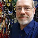
Unlike the IBM Q quantum computer shown in the second photo, KREQC isn't directly using quantum physics phenomena to implement its fully-entangled qubits. Well, I suppose we could argue everything uses quantum physics, but it's really just conventionally-controlled servos that implement Einstein's "spooky action at a distance" in KREQC. On the other hand, those servos allow KREQC to emulate the behavior rather well, making the operation easy to see and explain. Speaking of explanations....
Step 1: What Is a Quantum Computer?
Before giving our explanation, here's a link to a nice explanation from IBM Q Experience documentation. Now we'll take our shot....
No doubt, you've heard more than a bit (pun intended) about how qubits bestow magical computational abilities on quantum computers. The basic idea is that while an ordinary bit can be either 0 or 1, a qubit can be 0, 1, or indeterminate. By itself, that doesn't seem particularly useful -- and with just one qubit it isn't -- but multiple entangled qubits have the rather useful property that their indeterminate values can simultaneously cover all possible combinations of bit values. For example, 6 bits can have any one value from 0 to 63 (i.e., 2^6), while 6 qubits can have an indeterminate value which is all values from 0 to 63 with a potentially different probability associated with each possible value. When the value of a qubit is read, the values of it and all qubits entangled with it become determined, with the single value read for each qubit being randomly selected in accordance with the probabilities; if the indeterminate value is 75% 42 and 25% 0, then approximately 3 out of every four times the quantum computation is performed, the result will be 42 and the other times it will be 0. The key point is that the quantum computation evaluates all possible values and returns one (of potentially multiple) valid answers, trying exponentially many values simultaneously -- and that's the exciting part. It would take 64 6-bit systems to do what one 6-qubit system can do.
Each of KREQC's 6 fully-entangled qubits can have a rotational value that is 0, 1, or indeterminate. The equiprobable indeterminate value is represented by all the qubits being in the horizontal position. As a quantum computation proceeds, probabilities of different values change -- represented in KREQC by the individual qubits wobbling and assuming statistical positions reflecting the probabilities of values. Eventually, the quantum computation is terminated by measuring the entangled qubits, which collapses the indeterminate value into a fully determined sequence of 0s and 1s. In the video above, you see KREQC computing the "answer to the ultimate question of life, the universe, and everything" -- in other words, 42... which in binary is 101010, with 101 in the back row of qubits and 010 in the front.
Of course, there are some problems with quantum computers, and KREQC suffers them too. An obvious one is that we really want millions of qubits, not just 6. However, it's also important to note that quantum computers only implement combinatorial logic -- as opposed to what we computer engineers call a state machine. Basically, that means a quantum machine by itself is less capable than a Turing machine or a conventional computer. In KREQC's case, we implement state machines by controlling KREQC using a conventional computer to perform a sequence of quantum computations, one per state-visit in the state machine's execution.
So, let's go build a room-temperature quantum computer!
Step 2: Tools, Parts, and Materials

There's not a lot to KREQC, but you will need some parts and tools. Let's start with the tools:
- Access to a consumer-grade 3D printer. It would be possible to make KREQC's qubits using a CNC milling machine and wood, but it's a lot easier and neater to make them by extruding PLA plastic. The largest 3D-printed part is 180x195x34mm, so things are much easier if the printer has a large enough print volume to print that in one piece.
- A soldering iron. To be used for welding PLA parts.
- Wire cutters or something else that can cut small 1mm-thick plastic parts (the servo horns).
- Optionally, woodworking tools for making a wooden base to mount the qubits. A base is not strictly needed because each bit has a built-in stand that would allow a control cable to route out the back.
You don't need many parts nor materials either:
- PLA for making the qubits. If printed at 100% fill, it would still be less than 700 grams of PLA per qubit; at a more reasonable 25% fill, 300 grams would be a better estimate. Thus, 6 qubits could be made using just one 2kg spool, at a material cost of about $15.
- One SG90 micro servo per qubit. These are readily available for under $2 each. Be sure to get micro servos that specify 180-degree positioning operation -- you don't want 90-degree ones nor do you want ones designed for continuous rotation at variable speed.
- A servo controller board. There are many choices, including using an Arduino, but a very easy choice is the Pololu Micro Maestro 6-Channel USB Servo Controller which costs under $20. There are other versions that can handle 12, 18, or 24 channels.
- Extension cables for the SG90s as needed. The cables on the SG90s vary in length somewhat, but you'll need qubits to be separated by a minimum of about 6 inches, so extension cables will be needed. These are easily under $0.50 each, depending on length.
- A 5V power supply for the Pololu and SG90s. Normally, the Pololu is powered via USB connection to a laptop, but it can be wise to have a separate power supply for the servos. I used a 5V 2.5A wall wart I had around, but new 3A ones can be purchased for under $5.
- Optionally, 2-sided tape to hold things together. VHB (Very-High Bond) tape works well to hold the outer shell of each qubit together, although welding works even better if you never need to take it apart.
- Optionally, wood and finishing supplies for making the base. Ours was made from shop scraps and is held together by biscuit joints, with several coats of clear polyurethane as the final finish.
All told, the 6-qubit KREQC we built cost about $50 in supplies.
Step 3: 3D-Printed Parts: the Inner Part


All the 3D-printed part designs are freely available as Thing 3225678 at Thingiverse. Go get your copy now... we'll wait....
Ah, back so soon? Ok. The actual "bit" in the qubit is a simple part that is printed in two pieces because it is easier to deal with welding two pieces together than to use supports to print raised lettering on both sides of one part.
I recommend printing this in a color that contrasts with the outer part of the qubit -- black, for example. In our version, we printed the top 0.5mm in white to give contrast, but that required changing filament. If you'd rather not do that, you can always just paint the raised surfaces of the "1" and "0." Both these parts print without spans and hence without supports. We used 25% fill and 0.25mm extrusion height.
Step 4: 3D-Printed Parts: the Outer Part


The outer part of each qubit is a bit of a trickier print. First, these pieces are large and flat, hence subject to lots of lifting from your print bed. I normally print on hot glass, but these required the extra stick of printing on hot blue painter's tape to avoid warping. Again, 25% fill and 0.25mm layer height should be more than enough.
These parts also both have spans. The cavity that holds the servo has spans on both sides and it is critical that the dimensions of this cavity be correct -- so it needs to print with support. The cable routing channel is only on the thicker back side, and is constructed to avoid any spans except for a minor bit at the very base. The inside of the base on both pieces technically has an unsupported span for the inner curve of the base, but it doesn't matter if that portion of the print sags a little, so you don't need support there.
Again, a color choice that contrasts with the inner parts will make the "Q" of the qubits more visible. Although we printed the front with the "AGGREGATE.ORG" and "UKY.EDU" parts in white PLA on the blue PLA background, you might find the lower-contrast look of having them the body color to be more appealing. We appreciate you leaving them there to remind viewers where the design came from, but there's no need to be visually shouting these URLs.
Once these parts have been printed, remove any support material and make sure the servo fits with the two pieces held together. If it doesn't fit, continue to pick-out the support material. It's a pretty tight fit, but should allow both halves to be pushed flush together. Notice that there are deliberately no alignment structures in the print because even slight warping would cause them to prevent assembly.
Step 5: Assemble the Inner Part


Take the two inner parts and align them back-to-back such that the pointy pivot on the left of the "1" lines up with the pointy pivot on the "0." You can temporarily hold them together with 2-sided tape if desired, but the key is to use a hot soldering iron to weld them together.
It is sufficient to weld where the edges come together. Do this by first tack welding by using the soldering iron to drag PLA together across the edge between the two pieces at several spots. After the parts have been tacked together, run the soldering iron all around the seam to create a permanent weld. The two pieces should make the part shown in the image above.
You can check the fit of this welded part by inserting it into the rear outer part. You will need to tilt it slightly to get the pointy pivot into the side that doesn't have the servo cavity, but once in, it should rotate freely.
Step 6: Orient the Servo and Set the Horn

In order for this to work, we need to have a known direct correspondence between servo control and rotational position of the servo. Every servo has a minimum and maximum pulse width to which it will respond. You'll need to discover those empirically for your servos, because we are counting on the full 180-degree movement and different manufacturers produce SG90s with slightly different values (in fact, they also have slightly different sizes, but they should be close enough to fit within the space allowed). Let's call the shortest pulse width "0" and the longest "1".
Take one of the horns that came with your servo and trim the wings off it using wire cutters or any other appropriate tool -- as seen in the photo above. The very fine gear pitch on the servo is very difficult to 3D-print, so we instead will use the center of one of the servo horns for that. Put the trimmed servo horn on one of the servos. Now plug in the servo, set it to its "1" position and leave it in that position.
You probably noticed that the non-pointy pivot has a cylindrical cavity in it that is about the size of the gear head on your servo -- and somewhat smaller than the diameter of your trimmed horn center. Take the hot soldering iron and gently swirl it inside of the hole in the pivot and also around the outside of the trimmed horn center; you're not trying to melt either, but just to get them soft. Next, holding the servo, push the horn center straight into the hole in the pivot with the servo in what should be the "1" position -- with the inner part showing the "1" when the servo is positioned as it would be when resting in the cavity in the outer rear part.
You should see the PLA fold over on itself a little as you push the trimmed horn in, creating a very firm connection to the horn. Let the bond cool a little and then pull out the servo. The horn should now bond the part well enough so that the servo can freely spin the part with no significant play.
Step 7: Assemble Each Qubit


Now you're ready to build the qubits. Place the outer rear part on a flat surface (e.g., a table) such that the servo cavity is facing up and the stand is hanging over the surface edge so the outer rear part is sitting flat. Now take the servo and inner part attached by the horn and insert them in the rear outer part. Press the cable from the servo into the channel for it.
Once all that is sitting flush, place the front outer part over the assembly. Hook-up the servo and operate it while holding the assembly together to make sure nothing binds or is misaligned. Now either use VHB tape or use a soldering iron to weld the outer front and back together.
Repeat these steps for each qubit.
Step 8: Mounting


The little base of each qubit has a cut in the back that would allow you to run the servo cable out the back to connect to your controller, and the base is wide enough for each qubit to be stable by itself, so you could simply put extension cables on each servo and run them spread across a table or other flat surface. However, that will show wires connecting them....
I feel that seeing wires ruins the illusion of spooky action at a distance, so I prefer to hid the wires completely. To do that, all we need is a mounting platform with a hole under each qubit that is big enough for the servo cable connector to pass through. Of course, we'd like each qubit to stay where it's put, so there are three 1/4-20 tapped holes in the base. The intent is to use the center one, but the others can be used to make things more secure or if the central thread gets stripped by overtightening. Thus, one drills two closely-spaced holes in the base for each qubit: one to pass a 1/4-20 screw thread, the other to pass the servo cable connector.
Since 3/4" wood is most common, you'll probably want to use it for the top of the base -- as I did. In that case, you'll need a 1/4-20 screw or bolt approximately 1.25" long. You can buy them at any hardware store at a cost of about $1 for six. Alternatively, you can 3D-print them... but I recommend printing them one at a time if you do print them because that minimizes the defects in the fine screw thread.
Obviously, the dimensions of the mount are not critical, but they will determine the lengths of extension cables you'll need. KREQC was done as two rows of three qubits primarily so that the mount would fit in a carry-on suitcase, which is how we brought it to our IEEE/ACM SC18 research exhibit.
Step 9: Brand It


As a final step, don't forget to label your quantum computer!
We 3D-printed a nameplate in black on gold, which then was fixed to the wooden front of the base. Feel free to label yours by other means, such as 2D-printing of the attached PDF nameplate image with a laser or inkjet printer. It also wouldn't hurt to label each qubit with its position, especially if you get too creative about how you arrange the qubits on the base.
You might also enjoy handing out 3D-printed qubit keychains; they aren't entangled nor are they motorized, but they spin freely when you blow on them and make a great take-home reminder of a KREQC demonstration.


