

Introduction: A Collection of ANSI Terminals


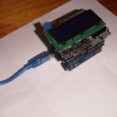
This project started as a way of displaying 80 column text on an LCD display suitable for running an old-fashioned word processor such as Wordstar. Various other displays were added ranging in size from 0.96 up to 6 inches. The displays use a single PCB as well as one Arduino sketch/program.
There is a serial RS232 connection for connection to a computer and a PS/2 socket for a keyboard. The displays were chosen to represent ones commonly available at reasonable prices. Depending on the memory needed the displays use an Arduino Nano, Uno or Mega.
Step 1: Summary of Displays

There are various displays with 480x320 resolution. This allows a 9x5 font and 80 column text. There are various boards with 320x240 resolution, with 9x5 fonts and also a very tiny 7x3 font to allow 80 column text. There are also smaller boards with 160x120 and 128x64 pixels. Also 20x4 and 16x2 text displays, and finally a 12x2 fourteen segment starburst display board.
Some displays use I2C, some are SPI and for the larger displays, a 16 bit data bus for faster update speeds.
Smaller displays use the Arduino Uno. Larger boards need more memory and so use a Mega. The starburst display board uses a Nano.
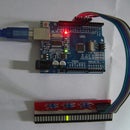
At this point I might mention the photos do not do justice to many of the displays. The tiny white oled display is very crisp and bright which made it harder for the camera to focus, and the starburst led display looks a lot sharper in real life.
Step 2: Hardware

The PCB has been designed to work with as many displays as possible. It is easy to change between a Mega and Uno using four jumpers. There are voltage divider resistors for displays that run on 3V. I2C pins are brought out in a group so that displays can be plugged in directly. The terminal runs at 9600 baud, and while this can be increased, many of the larger displays won't redraw much faster than this. The PS2 keyboard plugs in to a DIN6 socket. USB keyboards will also work with a cheap adaptor plug. You can do a simple loopback test by joining pin 2 and 3 on the D9 and then characters typed on the keyboard will appear on the display.
In some cases a PCB is not needed and it is possible to get things working with pre-made modules available on ebay, eg PS2 adapters, RS232 adapter boards and displays that plug directly into arduino boards.
There is also a separate board for the starburst led display - see later in this Instructable.
Step 3: Software
Below is a file called Package.txt This is actually a .zip file so download and rename it (Instructables doesn't allow zip files). Included is the Arduino sketch/program and this is a single program used by all the displays. There are also all the .zip files for each of the displays.
At the beginning of the program are a series of #define statements. Uncomment the one that corresponds to the display. Use Tools/Board to select Uno, Mega or Nano. Changing boards is as simple as changing one line in the code.
One of the challenges working with many displays is they all seem to need their own software drivers. These are all included in the package. Testing included taking the package and re-installing it on a new machine completely from scratch. You can also source code from Github and Adafruit and LCDWiki. There are a couple of instances where newer versions don't work so all the working versions are included in the zip. Occasionally there were instances where one driver stopped another one working as they used the same file name but different versions. There is a description in the comments at the top of program showing how to install each driver. Most are installed from the Arduino IDE with Sketch/Include Library/Add ZIP library and this takes the zip file and puts it in c:\users\computername\mydocuments\arduino\libraries.
If you are only using one display then some of these libaries won't need to be installed. At a minimum you do need the two keyboard files and the one for the particular display. Some displays share code. There are more detailed instructions in the comments at the top of the program, including getting the gfx library from Adafruit.
As all the displays use the same Arduino sketch, changing displays is just a matter of uncommenting one of the lines below:
// Different displays, leave one of the following uncommented<br>#define DISPLAY_480X320_LCDWIKI_ILI9486    // 3.5", 480x320, text 80x32, mega, 16 bit, plugs into mega 36 pin (and 2 power pins).http://www.lcdwiki.com/3.5inch_Arduino_Display-Mega2560. Slower than some of the options below but a more readable font and larger screen, 5sec bootup
//#define DISPLAY_480X320_MCUFRIEND_ILI9486  // 3.5", 480x320, text 80x32, mega, 5x9 font, only for mega but uses just the uno pins, power, D0-D14, A0-A5, nicer font than the ssd1289 40 pin module but a lot slower  https://www.arduinolibraries.info/libraries/mcufriend_kbv  https://github.com/adafruit/Adafruit-GFX-Library
//#define DISPLAY_320X240_MCUFRIEND_ILI9341  // 2.4", 320x240, text 53x24, mega
//#define DISPLAY_320X240_SSD1289_40COL      // 3.5", 320x240, text 40x20, mega, UTFT library (no fonts smaller than 8x12). Fast
//#define DISPLAY_320X240_SSD1289_53COL      // 3.5", 320x240, text 53x24, mega, 9x5 font, can edit font. Fast
//#define DISPLAY_320X240_SSD1289_80COL      // 3.5", 320x240, text 80x30, mega, tiny 7x3 font, can edit font, faster driver than the two above, fastest of all these as 16 bit direct drive to the display rather than spi/i2c
//#define DISPLAY_160X128_ST7735             // 1.8", 160x128, text 26x12, uno (ILI9341)  SPI 128x160
//#define DISPLAY_128X64_OLED_WHITE          // 0.96",128x64,  text 21x6,  mega, I2C, oled white on black (the tft library for this board plus all the code plus the keyboard runs out of program storage, even though the ram needs are very small, so only runs on a mega)
//#define DISPLAY_20X4                       //                text 20x4,  uno, LCD with I2C, text LCD https://www.arduino.cc/en/Reference/LiquidCrystal
//#define DISPLAY_16X2                       //                text 16x2,  uno, plugs into uno, uses pins 4 to 10
//#define DISPLAY_STARBURST                  //                text 12x2,  nano, starburst display with nano controller
//#define DISPLAY_320X240_QVGA_SPI_ILI9341   // 2.2", 320x240, text 11x8,  uno, large font, uno, 3v signals, 9 pin SPI display see Bodmer's Instructables - uno https://www.instructables.com/id/Arduino-TFT-display-and-font-library/  get the zip at the bottom and manually put the gfx and 9341 into the arduino library folder
Attachments

Step 4: The ANSI Standard

ANSI allows for simple commands to clear the screen, move the cursor around and to change colors. On a few of the photos there is a demo showing all the foreground and background colors. These are red, yellow, green, blue, cyan, magenta, black, white, dark gray, light gray, and the colors can be bright or dim so there are 16 foreground and 16 background colors.
It is quite possible to think about adding in a 'graphics' mode where you can draw much higher resolution pictures at the pixel level and with 256 or more colors. The main limitations are the internal memory of the Arduino and the time it takes to send a picture down a serial link at 9600 baud.
The code needs one byte to store the character and one byte to store the colors (3 bits for foreground, 3 for background, one for bright/dim and one for bold). So an 80x30 display will need 2400x2=4800 bytes, which will fit in a Mega but not a Uno.
Step 5: Displays


Above are photos of each individual display. There are photos from the front and the back of each display and they represent many of the brands available on ebay or similar. Some are I2C, some are parallel, some have larger fonts, some can display a full 80 columns suitable for Wordstar and other old word processing programs. There is more detail in the text of the arduino code.
Step 6: Schematic
Below are two files. They are named as .txt as Instructables doesn't handle .zip files. Download them and rename them as .zip.
There is the schematic and the board layout as pdf files. There is also a package for Seeed PCB. These are the gerbers and if you go to Seeed and upload this it should display the gerbers and you can then get PCBs made. The 14 segment board is large and costs quite a bit more, but the smaller one fits in the Seeed preferred 10x10cm format so is quite reasonable for 5 or 10 boards - in fact shipping costs more than the boards.
It is quite possible to use many of the displays without needing a PCB. There are PS2 socket modules, RS232 shields/modules all available on ebay or similar. Some displays like the I2C ones just can use a few hookup wires. Some like the SSD1289 displays come with adaptor boards and can plug straight into a Mega.
Step 7: Starburst Display

The starburst display is a larger board and uses a Nano and an number of 74xx chips to do the multiplexing. There were a lot of experiments to determine how many displays you could multiplex before they became too dim or the flicker became too noticeable. The displays came from Futurlec https://www.futurlec.com/LEDDisp.shtml The 14 segment displays can also do lower case letters and these can be modified in the code if needed. Rename these files from .txt to .zip
Step 8: Adding Code for Other Displays
It is possible to add in code for other displays. The first step is to get something, anything, to display. It can be a pixel or a letter. This mainly involves searching for drivers, downloading one, testing it, finding it will not compile, then uninstalling that driver so it does not cause confusion later, then trying a new one. The next step is to get a letter to display in the correct color, as some displays that look identical actually will invert the colors. Fortunately usually just one number in the startup code will fix this. Next step is to write a few lines to define whether to use a uno or mega, the display width, height, font size, keyboard pins and which driver files to use. These start at line 39 in the code and you can copy the format of the existing displays.
Next is to go down to line 451 and add in the startup code. This is where you set the background color and the rotation and initiate the display.
Next is to go to line 544 and add in the code to display a character. In some cases this is just one line, eg
my_lcd.Draw_Char(xPixel, yPixel, c, tftForecolor, tftBackcolor, 1, 0); // x,y,char,fore,back,size,mode
Next is to go to line 664 and add in the code to draw a pixel. Again, sometimes this is just one line eg:
tft.drawPixel(xPixel, yPixel, tftForecolor);
Finally go to line 727 and add the code to draw a vertical line for the cursor, for example
tft.drawFastVLine(xPixel, yPixel, fontHeight, tftForecolor);
The program sorts out things like how much memory to allocate for the screen buffer based on the screen width and the font size.
Step 9: Wordstar Demonstration
This was done using a CP/M computer, and there are many options available here. I needed something quick to set up, so used an emulation on an ESP32 (Google ESP32 CP/M). There are many other retro computers available, for instance, Grant Searle's FPGA emulation, and the RC2014 for those that prefer using a real Z80. Many retrocomputers tend to use a terminal program on a PC as the display, eg Teraterm. A lot of debugging this ANSI project involved running a terminal program and the ANSI program in parallel and making sure the screens looked identical.
Step 10: Further Thoughts
As displays increase in size they get slower and slower. Redrawing a character involves redrawing every pixel in that character as the background color has to be drawn as well, so everything comes down to how quickly you can draw a pixel. There are some tweaks, for instance if a display can't keep up with the data coming in, just store the text in the screen buffer and then do a full screen redraw when no more text is coming in. Many displays that you see for sale show a pretty picture on the screen, but what they might not show is how long it took to display that picture, and in some cases it can be 5 seconds or more. I2C and SPI are great for the smaller displays but anything over about 50 columns needs an 8 or 16 bit data bus.
Wordstar is a little unwieldy to use at 9600 baud and 19200 is much more usable for scrolling text, but the displays really can't keep up.
The fastest display I have used was on the Propeller chip with two 8 bit external 512k ram chips, to create a 16 bit parallel data bus. Each font was pre-loaded into the ram. A cascade of 74xx counter chips were used to clock out the data into the display. This meant there was no internal processing within the CPU fetching and outputting data, and the refresh rate was as fast as the Propeller chip could toggle a pin. Surprisingly, the displays were able to keep up with this,even at 20Mhz, and so it was possible to do a full screen update in only 30 milliseconds. That sort of rate is fast enough to do scrolling smoothly, like you see on mobile phones.
The Propeller chip was cutting-edge over ten years ago, and there are more options now including the ESP8266 and ESP32 which have large amounts of internal ram. However, those chips still don't have huge numbers of pins, so there still could be merit in using the old-skool way of an external ram chip that is clocked out to the display.
For larger displays it may be cheaper to use a LCD TV screen or VGA screen and look at some of the ANSI emulators that have been coded, eg the ESP32, which drive VGA directly.
I hope you find this project useful.
James Moxham
Adelaide, Australia
moxhamj@internode.on.net


