

Introduction: A New Perspective on 3D Printing!


A few weeks ago I saw a video on Reddit of someone that added a tiny camera to the extruder assembly. The view was truly mesmerizing! It was then I decided to make this myself! Finding a mount for the camera was not easy. All the mounts I found were either too far away from the nozzle or out of focus, so I decided to design my own using Fusion 360. Using a tiny plastic magnifying lens enabled me to get the camera closer while still being in focus. Please note that I used whatever parts were available in nearby hardware stores (in Norway). Therefore you need to see if you can find something nearby you or online! Without further a due let’s get started!
Supplies
- A 3d printer (This guide is specifically made for the Prusa MK3S+, if you have a different printer you have to figure out a different way of mounting the camera)
- 7mm Camera module (there is plenty to choose from on AliExpress, Amazon or Ebay)
- 3mm white LEDs (Preferably 3,3v ones so you can turn them on and off using Octoprint)
- Red and Black multithreaded wires
- Heat shrink tubing
- Soldering iron and solder
- Dremel
- 5-10x magnifying lens (I used a 5x one)
Step 1: Preparing the Camera Module


If you bought just the camera module you can skip this step!
I bought an “inspection camera” from Biltema here.
The camera is enclosed in an aluminum body making it 10mm wide. In my first versions I just simply mounted the entire camera to the extruder l, but I did not like the view. I decided to remove the camera from the housing using a Dremel to get the camera closer to the nozzle.
To do this you first need to determine the camera's orientation by plugging it into a computer. Open up the “camera” program that’s built into windows. Now turn the camera until the picture is the correct way, then mark the top of the camera module. This is where we will cut!
NOW VERY CAREFULLY cut along the housing, starting on the end where the wire comes out and stop at the middle of the housing. Then use a flathead screwdriver and put it into the groove you made and rotate it slowly to bend and widen the cut. Now if you did it correctly you should be able to easily pull the camera module out of its housing since it is not glued stuck. Great work! Now onto the lens.
Step 2: Preparing the Camera Lens


The hardest part about this step was finding a small enough lens to use. I purchased and dismantled a “thread counter” made for postage stamps. If you live in Norway you can find it on Clas Ohlson here.
Inside the thread counter, I found two 5x lenses. Any 5x plastic lens (or more than 5x if you want an even closer view) works. And since it’s plastic you can easily shape it using a Dremel.
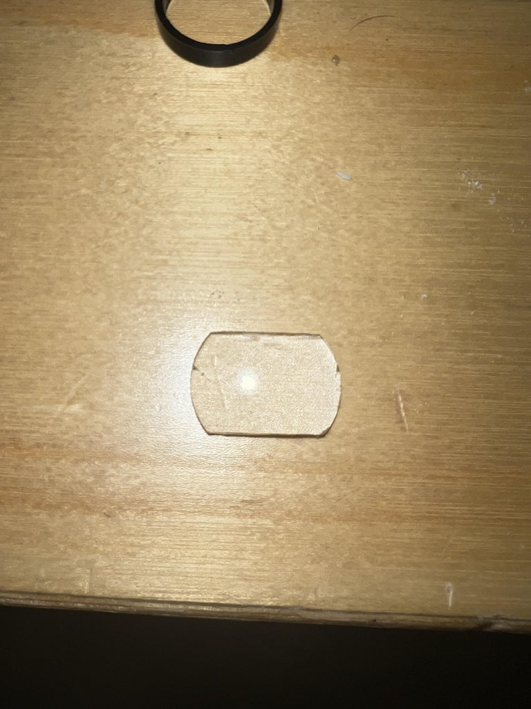
Since the lenses I had was 15mm wide I needed to file them down. When you do make sure to take off equally on both sides so we get the camera lens lined up correctly to the focal point of the lens (otherwise you might get a warped image), shave off a little bit at a time until the lens is 10mm wide. Now let’s move on to the fan shroud/camera mount. We’ll do the final shaping of the lens later.
Step 3: Print the New Fan Shroud

I found out that the Delta P fan shroud made by teookie over at Printables was ideal for this project! Bear in mind I am a complete novice in Fusion 360, but I managed to somehow make a model that works. You can find my remix (here). I printed mine in PETG at 0.2mm layer height and I used supports for the cylinder that holds the camera. Once it is done we can move to the next step!
Step 4: Soldering the LED’s and Mounting the Camera


There is two holes on each side of the fan shroud. They are pointed straight at the nozzle. Proper light is important for a good and crisp image.
When it comes to the soldering the LED’s it’s pretty straight forward. Just add a wire and heat shrink tubing to each of the LED pins. The shortest pin is - and the longest is +. We will hook this up to the Raspberry Pi later.
Step 5: Final Adjustments of the Magnifier Lens


We need to make some slopes on each side of the lens to fit the lens properly. I suggest only showing off a little at a time and test-fitting it each time until it fits snuggly. Be careful not to scratch the surface of the lens because that would leave marks on the video feed later (I did this with the first lens and had to trash it).
When the lens is the shape we need it’s time to glue it to the fan shroud. I tried using super glue first, but I WOULD NOT recommend this since it left a white residue on the lens and made it unusable. I ended up just using some good old hot glue (Keep in mind tho that I don't know if hot glue will not melt if you print with higher temp materials such as PETG etc).
Step 6: Mounting the New Fan Shroud


To mount the new fan shroud you also need to print the hotend cover part. Everything is in the Printables here. Follow the instructions in the pictures in this step to mount it to your 3D Printer. Remember to PID-tune your hotend after installation!
Step 7: Wiring and Connecting the LED’s to Raspberry Pi


I chose to add male and female connectors to the LED wires for easier maintenance later down the road. Other than that I recommend twisting the red and black wires to easily put them into the wire sock.
When it comes to where to connect it to the pi I chose pins 9 and 7 (see the diagram for which pins to use). This can later be programmed using a plugin called "OctoLight", to turn them on and off inside the Octoprint interface.
Step 8: Setting Up the Camera
This following is assuming you already have one camera connected to Octoprint. If you don't and this is the only camera you will use you can skip this step.
Prerequisites
You need:
- OctoPi 0.17 or later
- Warning: this is tested with 0.18, it should work with 0.17 but there may be some incompatibilities.
- SSH access or some alternative way of accessing the command line
- Plugin named MultiCam
- Of course, more than one camera!
Make a backup first. This guide touches on several configuration files with more than one point to go wrong. Don't take risks, make a backup.
Warning: this guide is incompatible with Obico (Formerly 'The Spaghetti Detective') premium webcam streaming. For this guide to work, you'll need to switch the plugin into 'Compatibility mode.
1. Creating the configuration files
OctoPi supports an infinite number of octopi.txt-style configuration files. They can be placed in /boot/octopi.conf.d/.
- Create the second one from the terminal:
cd /boot
sudo mkdir octopi.conf.d
sudo cp octopi.txt octopi.conf.d/webcam2.txt
Now you should have two identical files, one at /boot/octopi.txt and one at
/boot/octopi.conf.d/webcam2.txt.
2. Editing the original configuration file for a specific camera
- Find out the path to the camera by ID. This makes it much easier to stop /dev/video0 and /dev/video1 from switching on you.
- Run ls /dev/v4l/by-id, then save somewhere the long name of your camera. For example:
pi@ender5pro:~ $ ls  /dev/v4l/by-id/
usb-046d_0825_88C56B60-video-index0  usb-046d_0825_88C56B60-video-index1
I'll use the first one, usb-046d_0825_88C56B60-video-index0. Camera devices ending in index0 rather than index1 are preferred, as that is usually the device with video streaming.
Note: Not sure which device is which? You can run lsusb to match a name to an ID.
- Then edit /boot/octopi.txt:
sudo nano /boot/octopi.txt
- Set camera="usb" at the top, and the camera_usb_options line to indicate the device:
camera_usb_options="-r 640x480 -f 10 -d /dev/v4l/by-id/<device long id>"
Note: Using a Raspberry Pi camera? Set camera="raspi" at the top of the file, and you can ignore referencing the RPi cam by device ID. You'll still need to do this for the USB camera.
3. Editing the second configuration file
Two things need adjusting here: the port mjpg_streamer will be running under, and the device again.
- Find the long ID of the second camera, as you did for the first one.
- Editing /boot/octopi.conf.d/webcam2.txt:
sudo nano /boot/octopi.conf.d/webcam2.txt
- As above again, set camera="usb" and set camera_usb_options but this time using the ID for the second camera:
camera_usb_options="-r 640x480 -f 10 -d /dev/v4l/by-id/<device long id>"
- Adjust the port, by editing camera_http_options:
camera_http_options="-n -p 8081"
4. Test if it works
Restart webcamd using sudo service webcamd restart, and try and find your second camera under http://<your-ip>:8081. If it doesn't work, check the webcam log, /var/webcamd.log for details.
If it works, you can use the stream & snapshot URLs in OctoPrint:
- Stream: http://<your-ip>:8081/?action=stream
- Snapshot: http://<your-ip>:8081/?action=snapshot
Step 9: Set Up OctoLight

The setup of OctoLight is pretty straightforward. Just install the plugin and on the plugin settings, you choose PIN 7 as shown in the picture above. Depending on whether you switched the polarity on the wires you may need to check the "Inverted output".
Step 10: Enjoy!
You’re all done! Have fun with your new view! I would love to see your results by posting a make on my remix over at Printables.com! If you liked this and/or it helped you get your own nozzle cam please consider following me over at TikTok for more future content!
@caelestis3d

Runner Up in the
CNC and 3D Printing Contest


