

Introduction: ANTI THEFT ARDUINO SET UP


Hello everyone!
Today I will be teaching you how to set up a basic anti-theft system. As I am a beginner at using Arduinos, this set up is not a very advanced one, but I hope that whoever sees this will be able to pick something up from it and improve my idea even further and make it much better than what it is right now.
The reason why I want to make this is very simple. I would like to make this security system to prevent theft. Alternatively, this idea can also be used for other purposes such as attaching the sensor to the refrigerator door, when a mother wants to prevent her child from secretly eating ice cream.
Things you need for this set up:
1. Arduino board (can be any, in this case I am using Arduino UNO)
2. Vibration sensor
3. Active buzzer
4. Green LED and resistor
5. Red LED and resistor
6. Male-Male and Male-Female jumper wires
7. Breadboard
Step 1: Setting Up Ground and 5V From Arduino to the Breadboard.
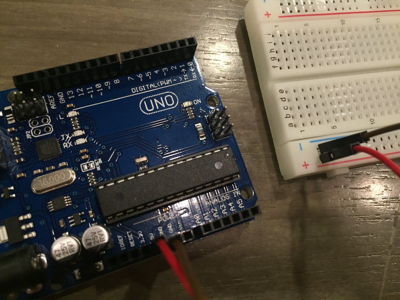
As in the picture, use 1 Male-Male jumper wire to connect the GND pin from the Arduino to the negative portion of the breadboard. Use another Male-Male jumper wire to connect the 5V pin from the Arduino to the positive portion of the breadboard. This is to allow the ground and 5V current to flow through the breadboard so that we can connect all our other stuff to it.
Step 2: Connecting the Green LED
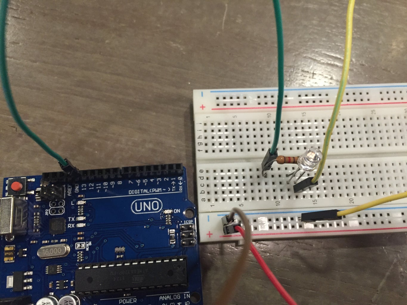
1. Use a Male-Male wire to connect from pin 13 to any spot on the breadboard (as in the picture)
2. Connect one end of the resistor to the pin below the end of the jumper wire (breadboard is horizontal view) and the other end on any pin to the right (same row)
3. Connect the positive end of the green LED (the longer leg) to the pin below the right end of the resistor and the negative end of the LED into the pin just to the right.
4. Take one Male-Male jumper wire and attach one end to the pin just below the negative leg of the LED and the other end to the negative row (where we previously connected the GND to the negative row)
(the picture might be more comprehensive than these written instructions, so do refer to the picture above!)
Step 3: Connecting the Red LED

1. Repeat the same steps as for the green LED, but this time using the Red LED, and connecting it to pin 12 instead of 13.
You will end up with the set up as in the picture above!
Step 4: Connecting the Vibration Sensor.
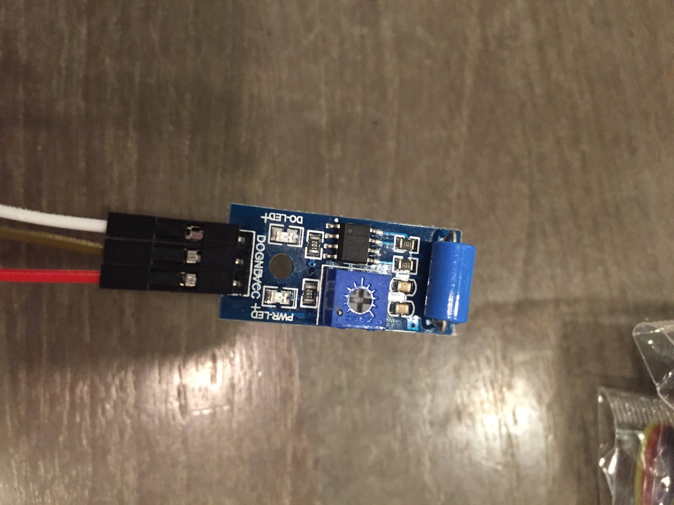

1. Using a Male-Female jumper wire, connect the male end to pin 3 on the Arduino, and the female end to the DO pin on the vibration sensor. This acts as the indicator as to where the vibration sensor is on the Arduino board. In this case, it is represented by pin 3.
2. Using another Male-Female jumper wire, connect the male end to the negative row on the Arduino (where the ground is running) and the female end to the GND pin on the vibration sensor.
3. Using another Male-Female jumper wire, connect the male end to the positive row on the Arduino (where the 5V is running) and the female end to the VCC pin on the vibration sensor.
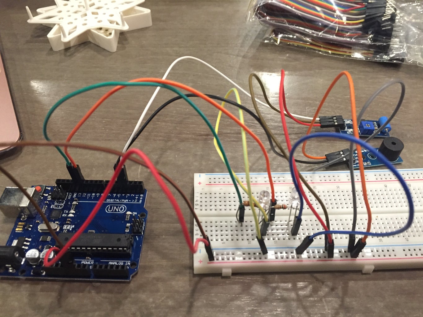
Your set up should now look something like this in the picture above.
Step 5: Connecting the Active Buzzer.
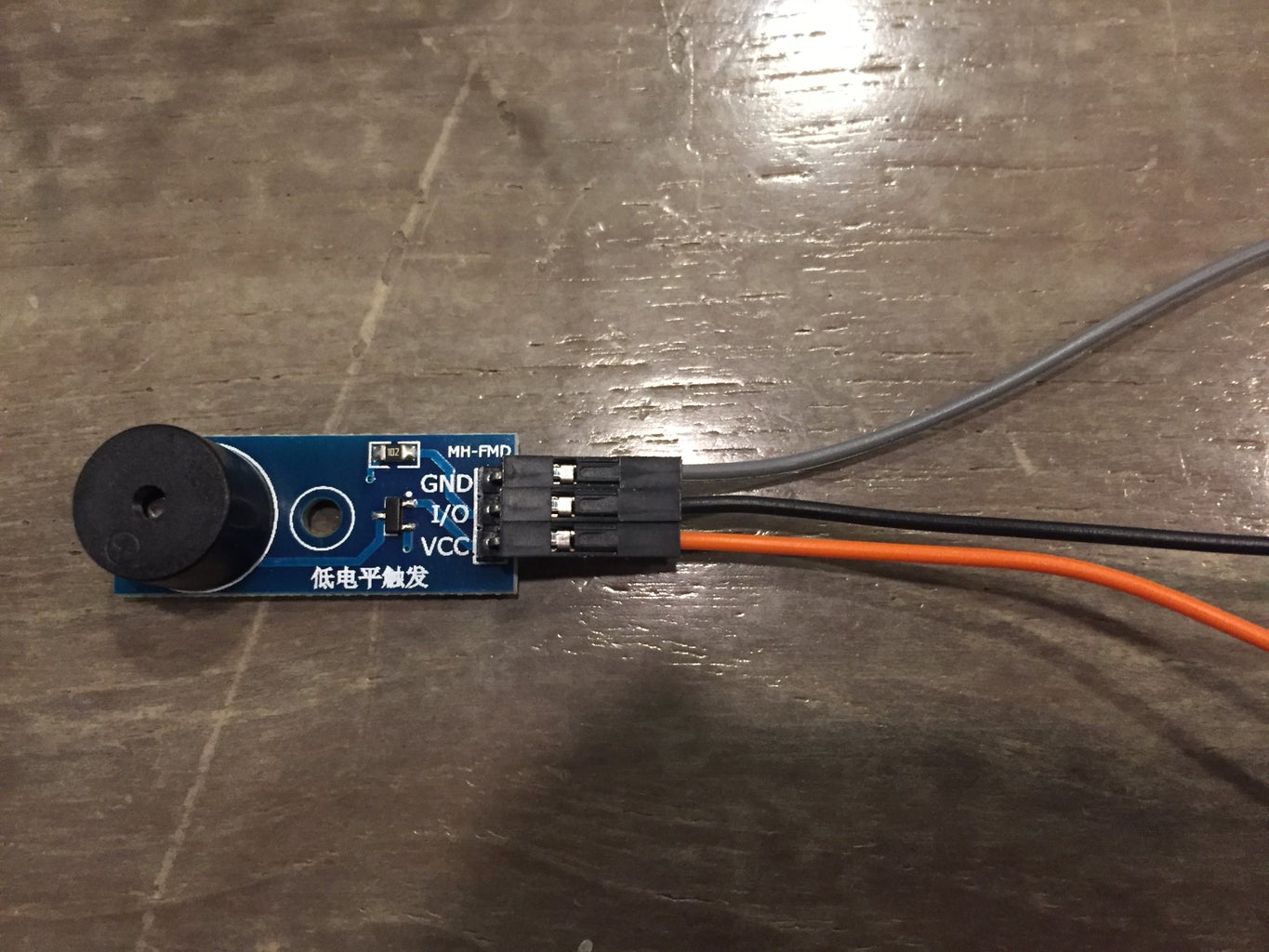
1. Using a Male-Female jumper wire, connect the male end to pin 4 on the Arduino, and the female end to the I/O pin on the active buzzer. This acts as the indicator as to where the active buzzer is on the Arduino board. In this case, it is represented by pin 4.
2. Using another Male-Female jumper wire, connect the male end to the negative row on the Arduino (where the ground is running) and the female end to the GND pin on the active buzzer.
3. Using another Male-Female jumper wire, connect the male end to the positive row on the Arduino (where the 5V is running) and the female end to the VCC pin on the active buzzer.
YAY! You are done with the physical set up!
Step 6: Putting in the Code…
Copy and paste this code into your Arduino App on your computer, and upload it onto the Arduino board.
int vibr=3; //introduces vibration sensor
int green=13; // introduces green LED
int red=12; // introduces red LED
void setup() {
pinMode(vibr,INPUT); // indicate vibration sensor as an input
pinMode(green,OUTPUT); // green LED is an output
pinMode(red,OUTPUT); // red LED is an output
}
void loop() {
int val;
val=digitalRead(vibr);
if(val==1)
{
int buzzer=4; // if the vibration is sensed, the buzzer will activate.
pinMode(buzzer,OUTPUT);
digitalWrite(red,HIGH);
digitalWrite(green,LOW);
delay(100000000);
}
else
digitalWrite(green,HIGH);
digitalWrite(red,LOW);
}
(code ends here)
CONCLUSION
Congratulations! You have made your very own movement detector which will activate upon physical contact, and the green LED will turn off while the red one turns on, and the buzzer will starting beeping as well!
This is how your final set up will look like…
Step 7:
Thank you for going through this project! :)
Attached above is a video of the project working! :)
One improvement that I will make in the future if I have the time would be to make this system wireless, so that we can attach the vibration sensor to the object wirelessly, let’s say the phone or the fridge door. This would be more practical as there will not be all these wires hanging loose around!
This work is licensed under a Creative Commons Attribution-NonCommercial 4.0 International License.


