

Introduction: ARDUINO Stepper Motor Controlled With Rotary Encoder and L293d or SN754410NE Chip


Stepper motor's are very useful for lots of diy projects. In most cases the microcontroller can control all the movements of the stepper, But in some cases you may want to manually control the stepper motor to set a start point, rotate a camera or fine tune something. To do this a rotary encoder is the perfect option.
This tutorial will show you how to connect a rotary encoder to your ARDUINO to control a H-Bridge that will run the stepper motor. This video shows the circuit in action: https://youtu.be/233LfyGHac0
PARTS YOU WILL NEED:
- 1 Rotary Encoder (one with a push button built in)
- 1 Push Button (only if your rotary encoder does not have a push button)
- 1 H-Bridge chip (L293D or SN754410NE, you can also use a pre assembled stepper control board)
- 1 Bipolar stepper motor
- ARDUINO board that supports interrupts
- bread board
- jumper wires
Step 1: Build the Curcuit
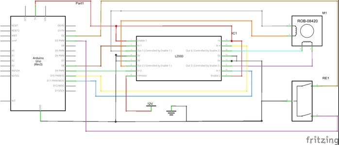
The picture above shows the circuit you will need to build, make sure the rotary encoder is connected to pins that support interrupts (on the uno its pin 2 & 3).
If you use a different H-Bridge chip or a pre built board you will need to modify the circuit accordingly.
For more info on H-Bridges and how they work check out this link: H-Bridge INFO
Step 2: The Code
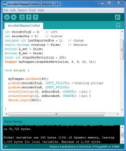
Now that you have the circuit built copy the code below and past it into your ARDUINO ide
#include <Stepper.h>
const int encoderPinA = 2; // right
const int encoderPinB = 3; // left
const int encButton = 4; // encoder push button
int encoderPos = 0; // counter
unsigned int lastReportedPos = 1; // change
static boolean rotating = false; // debounce
boolean A_set = false;
boolean B_set = false;
const int stepsPerRevolution = 200;
Stepper myStepper(stepsPerRevolution, 8, 9, 10, 11); //h-bridge pins
void setup() {
myStepper.setSpeed(60);
pinMode(encoderPinA, INPUT_PULLUP); //enabling pullups
pinMode(encoderPinB, INPUT_PULLUP);
pinMode(encButton, INPUT_PULLUP);
attachInterrupt(0, doEncoderA, CHANGE); //pin 2
attachInterrupt(1, doEncoderB, CHANGE); //pin 3
Serial.begin(9600);
}
void loop() {
rotating = true; // reset the debouncer
if (lastReportedPos != encoderPos) {
Serial.println(encoderPos);
lastReportedPos = encoderPos;
if (digitalRead(encButton) == LOW )
{
encoderPos = (encoderPos * 100); //change the 100 to how many steps
} //you want the stepper to move when
myStepper.step(encoderPos); //the button is pushed down
encoderPos = 0;
}
}
void doEncoderA() {
// debounce
if ( rotating ) delay (1); // wait a little until the bouncing is done
// Test transition
if ( digitalRead(encoderPinA) != A_set ) { // debounce once more
A_set = !A_set;
// adjust counter + if A leads B
if ( A_set && !B_set )
encoderPos += 1; //change the 1 to steps to take when encoder turned
rotating = false; // no more debouncing until loop() hits again
}
}
// Interrupt on B changing state
void doEncoderB() {
if ( rotating ) delay (1);
if ( digitalRead(encoderPinB) != B_set ) {
B_set = !B_set;
// adjust counter - 1 if B leads A
if ( B_set && !A_set )
encoderPos -= 1; //change the 1 to steps to take when encoder turned
rotating = false;
}
}
Now that you have every thing running turn the rotary encoder, If the stepper turns the opposite way than what you want just switch 2 wires on one side of the stepper motor (only one side not both).
Next push the button down and turn the encoder, Is should turn 100 steps in the direction you turned the encoder. If you want to change how many steps the stepper moves when you turn the encoder just look at the code, its commented at the 3 places you need to change it. When you change the push button value remember it will be multiplied by the normal steps value.
I hope this tutorial was helpful, if you have any questions or comments please leave them and ill get back to you ASAP.....


