

Introduction: An Advanced Approach to Arduino & AVR Programming


This instructable is a must read for everyone who is familiar with core AVR chips and Arduino.
Well,to be more specific,upon reading the instructable,you will be able to:
1)Know the proper difference between AVR and Arduino.
2)Programming Arduino using WinAVR & using it as a core AVR chip.
3)Burning Arduino bootloader to a Atmega328p chip and use it as a Arduino.
4)Burning Arduino bootloader to a Atmega8A chip and use it as a Arduino.
let's take a look on how these works....
Step 1: Materials Needed
1)An Arduino(I am using Uno Rev3).
2)ATMEGA328P or ATMEGA8A.
3)FTDI 5v breakout(I strictly recommend to use original FTDI chips.Not the cheap chinese breakouts!!!!)
4) USBasp programmer.(If you have arduino,then you don't need this).
5)16MHz crystal.
6)22pf x 2
7)100nF x 1
8)10K1/4w Resistor x 1
9)150R x 1
9)Breadboard.
10)Some jumper wires
Step 2: What Is the Difference Between Core AVR & Arduino
This is the first basic question for those who are comparatively new to Arduino/AVR stuff....
AVR:
Well,AVR is a family of microcontrollers from "Atmel Semiconductors"
Like a family contains many members,the AVR family also contains different type of microcontrollers.They all follows Havard architecture.They are 8 bit microcontrollers.(There are 32 bit AVR chips also).
AVRs can be mainly classified in three groups
1)tinyAVR.(lower pincount with lower programming space)
2)megaAVR.(with medium programming space)
3)xmegaAVR.(higher programming space with some extended features like "DMA").
So there are many chips under these 3 groups.
Like for Ex-.
Atmega8/Atmega16/Atmega32/Atmega328 are all different members of mega family with some slightly different characteristics from each other.
For say, Atmega328p has 32k flash/1k EEPROM/2k SRAM whereas Atmega8 has 8k flash/512 byte EEPROM/1K SRAM although both have same no of pincount(28).
On the other hand Atmega32 has also 32k flash like Atmega328p but with higher pincount(40).
ATTINY45 is one popular microcontroller from tinyAVR family with only 8 pins and with 4k flash/512 byte EEPROM & SRAM.
So you have to choose Microcontroller as per your circuit needs.Like if you want to blink a single LED,then ATTINY45 is perfect but if you want to drive a complex LCD like 128x64 or 20x4 then you must choose mega8/328/32.
This microcontrollers are blank chips with nothing programmed in their flash/bootloader.Now what the hell is bootloader?I will discuss it later.
You have to design a proper power circuit to feed it,supply it clock in order to run it.Also you need some sort of programmers to burn programs into them.
They can be programmed in many different ways,we will see in the upcoming steps how it can be done.Also you need some sort of IDE where you can write your program.Winavr is an IDE.Also Atmel studio is another IDE for writing programs for Atmel microcontrollers.
We will choose WinAVR to program our core microcontrollers.
ARDUINO:
We can say that Arduino is platform (including hardware & software) mainly used for prototyping.The great benefit of arduino is that this is a "open source".
Well,i guess i have to focus more light on this....because here comes the main difference between AVR and Arduino
For instance,Arduino UNO rev3 is a board which contains a AVR Microcontroller and all the necessary peripherals to make it work like as i said before,the power supply,clock circuit etc.The microcontroller used here is a Atmega328p.
Also there is a on board "arrangement" to program the mega328p without a programmer.Now what is the arrangement????
There is a simple USB to Serial converter on board by which you can program the mega328p.But how???This is where,the "bootloader" comes in.
"bootloader" is a piece of small program situated in a particular area of the microcontroller's flash.When the chip is restarted/powered on,the chip first enters into the bootloader area(This activity must also be programmed via fuse bits) and executes the code written into it.But how the code is able to program the chip itself???
For say,the code is written in such a way,that it waits for the programming bytes to arrive from the USB to Serial converter.When programming bytes received,it stores the bytes in it's program flash and when all the bytes received,it restarts itself and executes the code which is newly written into program flash.
But a question now arises that after the programming,if the mega328p is booting from the program flash(avoiding the bootloader),then how it can be programmed in the next cycle??
The answer is pretty simple,the mega328p never jumps to starting location of the program flash first.It always jumps to the bootloader section first and wait there some time for the arrival of databytes via serial port.If data arrives within the timeperiod,then it starts to program itself like stated before,If data doesn't arrive within the particular time,then it leaves the bootloader section and starts code executing from program flash.
The byte sending sequence is known by both the bootloader and the ArduinoIDE.This is how arduino programming works without the help of a programmer.
BUT........
In order to burn the bootloader into AVR's flash,some kind of programmer(Either Parallel/ISP) must be used for the first time.This is where comes the necessity of the standalone programmers.
Now about the IDE of the arduino.
In Arduino IDE,There are many kinds of boards to choose from.Each board uses different type of microcontrollers.Like the UNO rev3 board uses Atmega328p.The mega2560 uses Atmega2560 etc etc.
Then there comes another exciting part of the Arduino."The library".The libraries are bunch of programs to drive different modules of the microcontroller(Like TWI ,SPI ,PORT etc)or to drive another external Hardware like LCD,Stepper motor,Different types of sensors and many many others.In order to make the microcontroller work,you have to write some nominal codes using the functions from the existing library.Also the language used in the Arduino IDE is C/C++.But you don't have to directly interact with the hardware of the atmega.These are taken care of in the background.The commands are much more simpler than using core 'C'.I will program the atmega chip in two different IDEs later.
On the other hand,if you have to program a core AVR with Winavr or such other C based IDE,then you have to know the proper architecture,hardware,modules of the microcontroller and then only you can program it.But why one would go in such a coplexity????This is a million dollar question.....
Have you ever felt,that you are only using other's written code/functions and you are unable to modify it as per your needs or you are unable to see how the total program works in the background or have you ever felt the need of code execution line by line???
If you ever felt any of those mentioned above,then its time for you to write core 'C'code for you AVR.
Also if you want to unleash the power of the low level core AVR programming with your own written library/code and want to modify the codes as per your needs and parallelly want a better understanding of your whole code....then you must play with core AVR programming.
Hope i have cleared your doubts about the Arduino and AVR stuff.Now time for a little break before entering into the next section......
Step 3: Programming the Arduino UNO Rev3 From WinAVR Environment


In order to program the arduino via WinAVR,you have to first download it from here.
Before proceeding further,you must have a look at the pin mapping of the core Atmega328 chip as the Arduino UNO.Just take a look at my attached pic.They are all arranged in the necessary order.Although the chip is marked as Atmega168 but Atmega328 also has the same pin mapping.
Here we will blink the onboard LED using WinAVR.The LED(marked 'L' on board)is connected as shown in the third image.
If we draw only the LED circuit extracted from the board(except all other components),then the circuit will be looked like that in the third pic.The op-amp used here is configured as a buffer i.e whatever it will get in pin #5(0/1),it will exactly give the same output at pin #7.The main reason behind this is to supply sufficient current to drive the LED.
So u can see that the atmega328p pin #19 is driving the LED via the op-amp.As you can see that it is marked digital13 in arduino pinout and PB5 in AVR pinout.Just keep it in mind,we will discuss about it shortly.
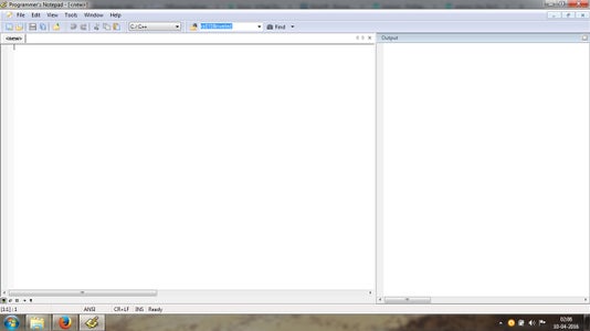
Now we will go back where we were.After downloading the WinAVR,install it.Before proceeding further,Create a Folder named "Blink" at desktop.This is where we will keep all the files regarding our WinAVR blink project.Now go to Start>all programs>WinAVR-20100110.Click on it and run the Programmer's notepad.Now click on File>New>C/C++ and you will see something same like pic4.Now save it by clicking File>Save As and notify the path to Blink folder at desktop and give it filename as main.c.Now we have our 'c' file.Look just under the file menu,the name should be changed to main.c.
Now here comes the main part,the program will be as below. As i am not giving any tutorial regarding AVR architecture/AVR programming tutorial, i will only give short explanation for each line.If you want to know more about
particular AVR familily architecture/programming,then i will mention some good books/link at the end of this expendable.
Ok,for now,let's start our blink program in WinAVR.
#include //This is regarding all the necessary hardware definitions for the AVR.
#include//This is regarding the delay functions.
int main(void) //starting of main
{
DDRB |=(1<<5); //Configuring PB5 as output by Writting 1 to Data direction register(DDR).
while(1) //entering into infinite loop
{
PORTB ^=(1<<5);//Toggle the state of PB5.
_delay_ms(1000);//Delay 1s
}
}
Now minimize the programmer's notepad.
Click on Start.in search,type "Mfile"and press enter.Now a new Makefile will open.Now please pay attention regarding this part,as this is probably the most cruicial part for the Arduino programming from WinAVR IDE.
Basically the Makefile contains all the necessary settings to burn the program to the chip.Now follow these steps as described.
1)Click on the "Makefile" tab and the click on the last option i.e "Enable editing of Makefile".Now you will be able to change the parameters of the Makefile.Check Pic #5
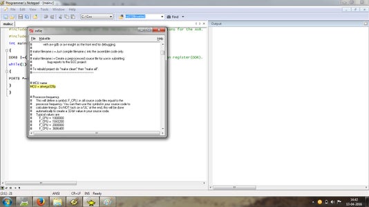
2)Now click again on the "Makefile " tab and click on "MCU type>ATmega> and choose the MCU as Atmega328P from the list.Click on File>save.
3)Now u can see,that the MCU will be highlighted with Yellow colour in the Make file as on Pic #6.
4)Just under the MCU=atmega328p,there will be #processor frequency.At the last line of the #processor frequency i.e F_CPU=8000000(by default),change it to 16000000 carefully(Just omit the 8 and type 16.Beware of the 0s.There will be 6 0s.)Check Pic #7.This is because the arduino runs on 16MHz.Click on File>save.
5)Now click on Makefile tab and select Programmer>stk500v2.Now inside the Makefile,this willbe showing "
AVRDUDE_PROGRAMMER = stk500v2" in yellow highlight.Omit the stk500v2 and type "arduino".Check pic #8.Click on File>save.
6)Now attach your arduino Uno Rev3 to your PC.Minimize the Makefile and right click on My computer icon.Then click on manage and then click on device manager.Take note of the port no of the arduino uno.Check pic #9.This will vary from mine to yours.Mine was 22.
7)Now resume the Makefile.Just next where you typed "arduino",there will be port # definition for the avrdude.This will be showing as "AVRDUDE_PORT = com1".Now omit the '1' and type Your arduino port #.I typed "22".Click on File>save.Check pic #10.
8)Now after some lines of the port definition,there will be a line "#AVRDUDE_VERBOSE = -v -v".Now just after this line,type "AVRDUDE_BAUD = 115200".Click on File>save.Check pic #10.
By adding this line,we are defining the baudrate for the serial communication between the on board Atmega328P and the on board USB to Serial converter of the arduino uno.This may be different for different Arduinos.
9)The next line will be "AVRDUDE_FLAGS = -p $(MCU) -P $(AVRDUDE_PORT) -c $(AVRDUDE_PROGRAMMER)".
Add "-b $(AVRDUDE_BAUD)" at the end of the previous line preceded by a "space".The final line will be looking like below:
AVRDUDE_FLAGS = -p $(MCU) -P $(AVRDUDE_PORT) -c $(AVRDUDE_PROGRAMMER) -b $(AVRDUDE_BAUD)
Check Pic #11.
Now you are ready to rock.Click on the File>Save as of the Makefile and navigate to inside of "Blink" folder and give Filename as "Makefile"and save it.DO NOT FORGET TO GIVE THE FILENAME AS "Makefile".Check pic #12.Now close the Makefile.
10)Now resume the Programmer's notepad and first click on "tools>[WinAVR ] Make All".If u did all exactly as my description,then the Make process should be without error and programmer's notepad page should look as on Pic #12.
11)If the Make process completed successfully,then it is time to burn the program.Now click on "tools>[WinAVR] Program".The progress window should show the reading process.Then it will show the AVR flash writting process.After that,it should show the flash verification reading process.Check pic #13.
If everything is right,the Arduino LED will start blinking in 1 sec interval.
Bingo....now you are an AVR expert.
Another thing,save the Makefile in a secure location.Because you can simply copy-paste this makefile (without that much editing) for all your different future Arduino-WinAVR programming projects.
Step 4: Burning Arduino Bootloader Into Atmega328P


As the article describes,this step is for those guys who want to make an Arduino on a breadboard using nominal components and still can get benefit of the Arduino libraries.
Basically after burning the arduino bootloader into the core atmega328p chip,you will no longer need a special programmer(USBasp/Parallel/Arduino as ISP) to burn program to the atmega328.Afterwards,you can use a FTDI 5v breakout to burn programs to the atmega328p either from Arduino IDE or fromWinAVR IDE as described in the last step.
The chip will perform as an Arduino on a breadboard.Although there are numerous instructables on this topic but i thought to cover this topic within my instructables.
First,there are two possible ways to burn the Arduino bootloader into the core Atmega328p.
1)Using Arduino as a programmer.(Obviously you will need an arduino board for this).
2)Using USBasp AVR programmer(If you don't have one,you can borrow it from someone.Although i would recommend to collect one in your arsenal as sometimes they really come in handy).
In this step,we will see that how to burn a bootloader using an Arduino board.Steps are as follows:
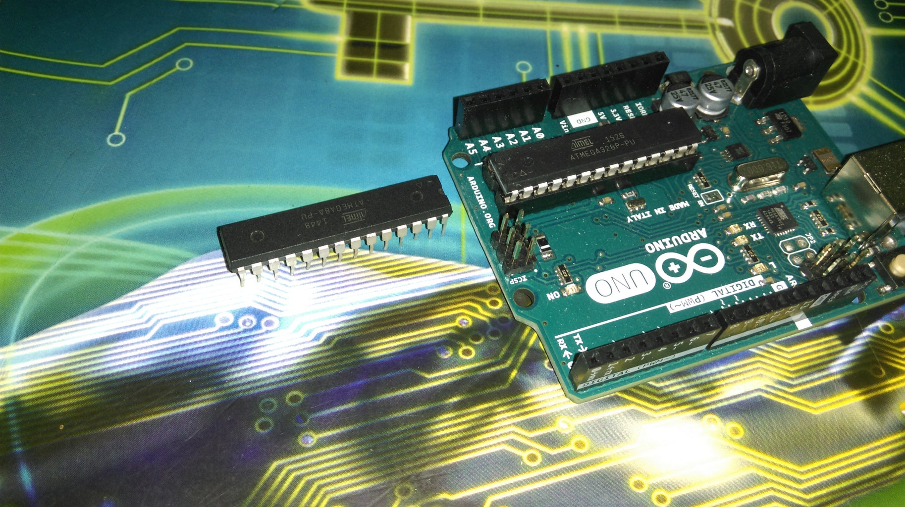
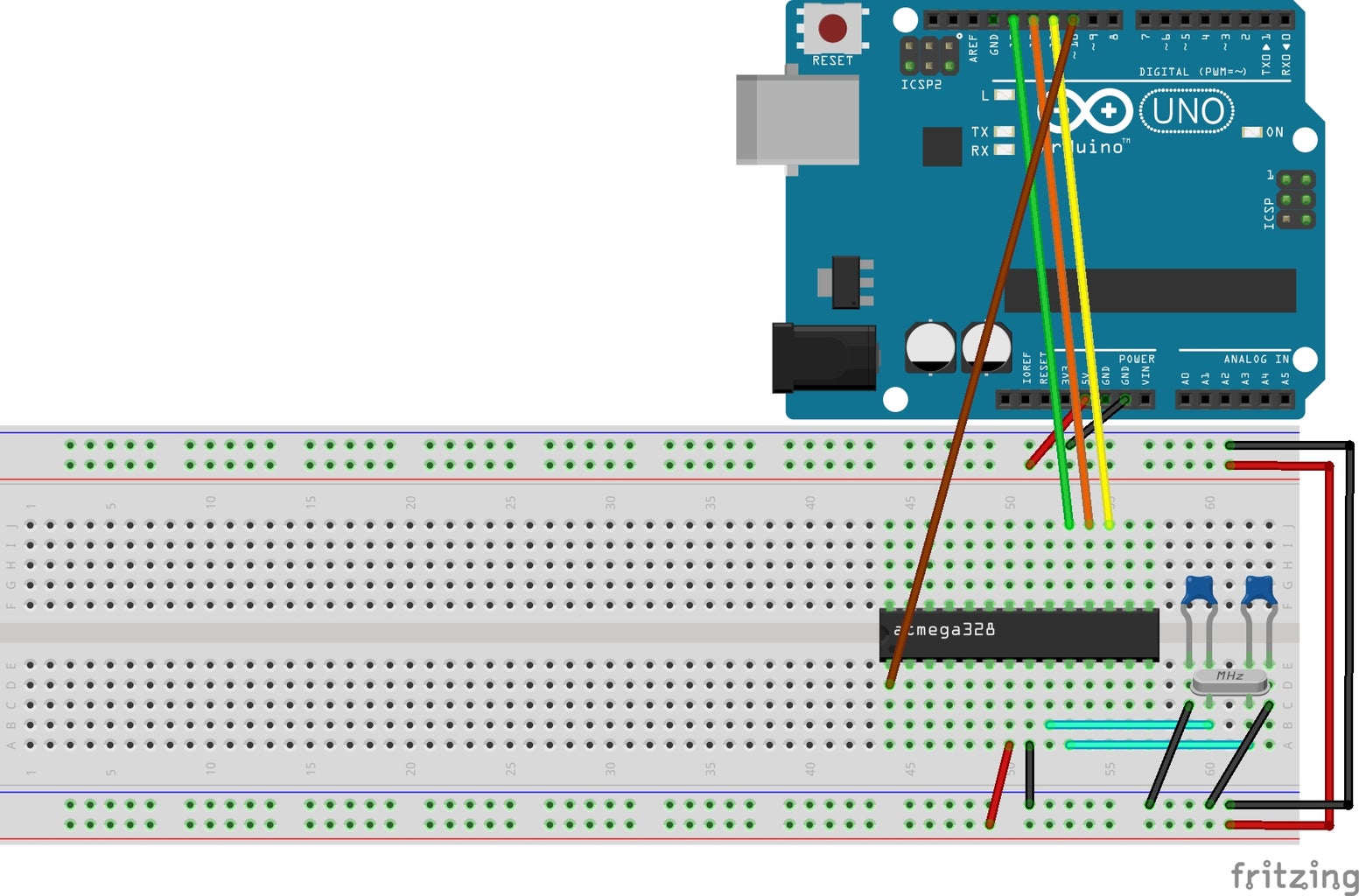
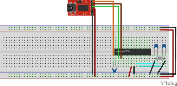
1)Setup the Arduino UNO & the core Atmega328p in the breadboard as shown in the first PIc.The crystal is 16Mhz crystal and the two caps are 22pf.No external power is needed.You can power the target chip from the Arduino board.Basically the Arduino UNO will behave as an ISP AVR programmer.In order to do that,we will have to program the UNO board.
2)In order to program,open the Arduino IDE and Click on "File>Examples>ArduinoISP>ArduinoISP" and maximize it.
3)Now select board by clicking "Tools>Board:>Arduino/Genuino UNO"(Mine was Arduino UNO,Select as per your board).
4)Select the Port at which the Arduino is attached to by clicking "Tools>Port".(Please refer to the previous step how to find the port from Device manager).
5)Now click on "Sketch>Upload".The IDE will first compile the program and after that it willupload the sketchto your Arduino board.After the sketch is uploaded,now your arduino will perform as a AVR ISP(In system programming) programmer.
6)Now again select board as Arduino as described in step 3.But remember,this time you are choosing the board depending on the target chip (In our case Atmega328P to be run @16Mhz) on which the Bootloader to be burned.
7)Now click on "Tools>Programmer>Arduino as ISP"(There is a option named ArduinoISP.Don't confuse with that)
8)Now click on "Tools>Burn Bootloader".
If everything is fine,then in the progress window at the bottom of the Arduino IDE,it will be shown something like "Done burning bootloader" .Please refer to Pic #2.Now close the Arduino IDE.
Now it's time to test a Blink LED program.Now as the bootloader is burnt already,we will use the FTDI 5v breakout to upload the Arduino Blink sketch into the Atmega328P.
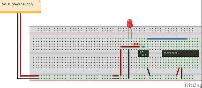
Disconnect the Arduino and connect the FTDI to the Atmega328P as shown in the Pic#3.The DTR pin is connected to a 100nF cap.This time also,we will power the test breadboarded arduino via the FTDI 5v breakout.Please notice one thing,that the Reset pin of Atmega328p(Pin #1) is connected to the DTR pin of the FTDI via a 100nF cap.This arrangement is done to reset the Microcontroller in order to start a new programming sequence.
Now the decription to burn the Blink sketch in our new breadboarded Arduino is as follows:
1)Open Arduion IDE.
2)Connect the FTDI to the PC.Checkout the Port no as decsribed in the previous step.
3)Select the board "Tools>Board:>Arduino/Genuino UNO" as we are using Atmega328P @ 16Mhz.
4)Click on "Tools>Port>"your FTDI connected port".Mine was port #10.So i choose "Tools>Port>COM10.
5)Now click on "File>Exampleas>Basic>Blink"
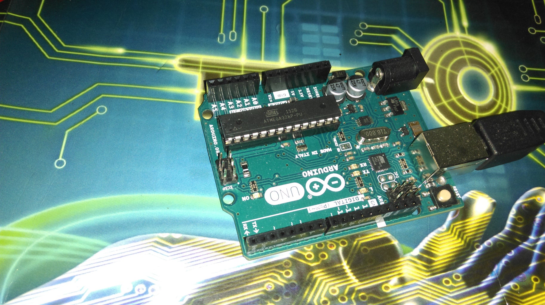
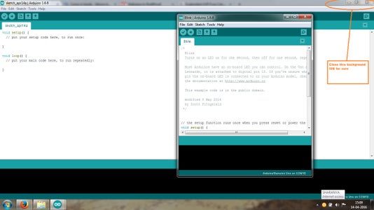
6)Now close the Arduino IDE in the background as shown in Pic #4.
7)Now maximize the Blink sketch and click on "Sketch>Upload".Your program should be compiled and uploaded successfully.Now surely close the Arduino IDE.
8)Now disconnect the DTR/Tx/Rx line of the FTDI from the breadboard and attach the LED via the resistor from Pin #19 of the Atmega328P.Refer to Pic #5.Here i have omitted the setup with LM358 as in the Arduino official boards as Atmega can drive a single LED successfully.Now your LED should blink with 1s interval.Unplug the whole setup from USB and replug again.
The reason behind not attaching the LED at startup while programming the chip and removing the DTR line after programming is that while i was experimenting,i saw that the The AVR was being randomly resetted whenever i was opening the Arduino IDE to program it.I think the Arduino IDE was sending Reset signal to the FTDI randomly.That's why i recommend to disconnect atleast the DTR line upon completion of successful program upload to avoid accidental reset.
Step 5: Burning Bootloader to Atmega8
If you want to use Atmega8A as Arduino,then this step is for you.This step is a little bit difficult as compared to burning bootloader to Atmega328.
There is a bug in the recent Arduino IDEs regarding the Fuse bits of the Atmega8A.Basically there are three types of fuses present in the Atmega328p namely 1)lfuse 2)hfuse 3)efuse.
The third type i.e efuse is not present in the Atmega8A.If you want to burn bootloader into an Atmega8A,then the IDE will report error message regarding the efuse and the burning bootloader process will be stopped.
To overcome the issue,please do the necessary steps as described in this link.The steps are really easy if you follow minutely.
If you followed the steps described in the link,now it's time to burn the bootloader.The process are as follows:
Setup the hardware as described in the Atmega328P bootloader burning step.
1)Close Arduino IDE after the steps described in the link.Reopen it.
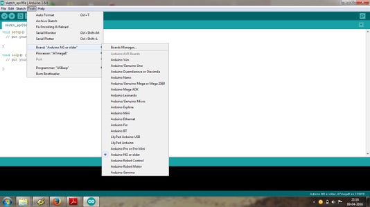
2)Click on "Tools>Boards>Arduino NG orOlder".
3)Now click on "Tools>Processor>Atmega8".
4)Connect your Arduino to PC and check the Port#as described previously.
5)Now click on "Tools>Port>"Your arduino port".Mine was 22.So i clicked "Tools>Port>COM22.
6)Now select the programmer(Assuming you have burned the arduino ISP sketch on your Arduino board)by clicking on "Tools>Programmer>Arduino as ISP".
7)Click on "Tools>Burn bootloader".
If everything goes fine,then the bottom progress window will show "Done burning bootloader".
You are done.Now upload the Blink program to Atmega8 via FTDI 5v brekout as described in the Atmega328P blink upload in previous step.Just remember,select the board as "Tools>Boards>Arduino NG orOlder" and choose the processor as "Atmega8".
Voila......the LED should blink after uploading the blink sketch to arduino.
Step 6: Burningthe Bootloader Via USBasp
If you don't have an arduino and instead have a USBasp avr programmer,then the settings willbe as follows for uploading bootloader toeither Atmega328P/Atmega8A.
1)Connect the MOSI/MISO/SCK/RESET/VCC/GND of the USBasp programmer cables to 17/18/19/1/VCC/GND Pins of the AVR.
2)Follow the steps as described previously for Atmega328P/Atmega8A but just select the Programmer as "Tools>Programmer>USBasp"
You are done.Now follow the remaining steps as described previously.
Step 7: Final Words.....
Before saying goodbye,i just want to share some facts regarding this expendables.
Many time while programming the AVR chips,i found it very difficult to attach the USBasp programmer with all those cables to the breadboard.If you burn arduino bootloader to the target chip,then it is relatively easy to burn hex files.
In many cases,when programming AVRs from the WinAVR IDE,the programming may fail returning "Not in sysnc" error.Just try with different baudrate like 19200/57600 instead of 115200.
Read some good books if you want to program core AVRs.Read "The AVR microcontroller & embedded systems" by Mazidi.By far it is written in the most basic way as compared to many other complex books available.Also Please read the datasheets carefully before any sort of programming.Datasheet is the best friend of a microcontroller programmer.ATMEL's datasheets are great in terms of info.If you try to program core AVRs,at first glance,it is far more complexed as compared to Arduino programming.But believe me,if you get used to it,then it is the most effective way.The opportunities are endless.
Though i have tried to be as much elaborate as possible,but in case you need any support,feel free to ask.As i am not a AVR/Arduino expert,i will try my level best to answer your questions.
Happy burning..........
Rgds//Sharanya


