

Introduction: ArduRadio AlarmClock


This is the evolution of the " DIY Alarm Clock " (https://www.instructables.com/id/DIY-Alarm-Clock) with the addition of the radio (TEA 5767)
Navigating the Web I found a beautiful project of an FM radio with Arduino (https://www.instructables.com/id/Make-an-Arduino-FM-Radio-using-TEA5767/#CLPEZERIX0PVJW6), and since I like music I decided to update my "Alarm Clock".
Step 1: COMPONENTS
- Arduino Uno or Arduino Standalone
- Philips hue TEA 5767 FM Module for Arduino
- STMicroelectronics TDA7297 amplifier Dual-Channel AC/DC 12V
- Real Time Clock (RTC)
- Display LCD 20 x04 with module I2C
- Linear Regulator (7805)
- diode 1N4007
- Button switch 6
- LED
- Resistor 220 ohm
- Jack Stereo female
- wires
- 1 electrical junction boxes 120 x 80 x 50 mm
- 2 electrical junction boxes 100 x 100 x 50 mm
Step 2: TEA 5767


The "TEA 5767" card, purchased for a few € on Aliexpress, carries out most of the work, is connected to Arduino to pin A4, A5 (protocol I2c) and a Stereo TDA 7297 amplifier.
The TEA 5767 is very small and I had to do a lot of effort to fit a card with a thousand holes
Step 3: Scheme


I took a lot of inspiration from the project "erik12892" but I also made several changes.
In addition to the P1, P2, P3, P4 buttons on the Alarm Clock, I have added 2 more than I need:
• P5 to change stored stations, I have only entered 4, but you can increase, it by changing the code a bit
• P6 since the TEA 5767 card consumes very little current, has been used to turn the radio on or off via Arduino, in order to use an auxiliary input (mp3, phone, etc.)
To change the radio frequency, use the buttons P2 = More, and P3 = Less.
To stay low with the measurements, I built an Arduino Standalone.
I enclose the electrical diagram, the Fritzing scheme and the PCB drawn in EXCEL.
Step 4: Construction


As with many of my designs,I used the electrical junction boxes, there are different sizes and shapes, I used a 120 x 80 x 50 mm for the container and two 100 x 100 x 50 mm for the speakers.
The speakers were recovered from an old cathode-ray monitor The 3 boxes have been joined by cable glands and M3 screws.
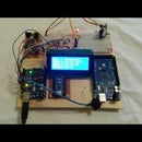
Step 5: Test


Before building the PCB, and putting it all in the box, I did several tests with the prototype chopping board.
Step 6: Assembling


Three wires were welded to the amplifier to be connected to the TEA 5767 to respective L, R, and GRD
Arduino, TEA5767, Amplifier, Buttons, and Display, everything was assembled as from attached pictures. As an antenna I used an electric wire up to 30 centimeters
Step 7: Arduino Code
Code < here >
Libraries:
Wire.h: from Arduino
IDE RTClib.h (https://github.com/adafruit/RTClib)
LiquidCrystal_I2C.h (https://github.com/fdebrabander/Arduino-LiquidCrystal-I2C-library)
TEA5767Radio.h (https://playground.arduino.cc/Main/TEA5767Radio)
Step 8: Work in Progress

I just bought a "DFPlayer Mini MP3 Player" ....


