

Introduction: Arduino Atari Adaptor


Recently I've become more and more interested in vintage computer tech. One of the most interesting and influential classic pieces of tech is the Atari 2600 which was first released in 1977. Unfortunately, I never got the chance to play this as a kid mainly because by the time I was old enough to talk it was already over 20 years old!
Recently I did some digging and managed to find one of these online for a pretty good price but as with a lot of old technology as I plugged it in it just went poof.
That is one of the risks when it comes to playing and collecting old tech, because it's so old, there's no guarantee it will work and you may end up spending good money just to make your house smokey. The obvious solution is to just download an Atari emulator that can emulate the old system. For the most part, this works great, however, it doesn't feel as authentic as playing on the original hardware especially because of the keyboard.
So I thought a great solution is to make an adaptor that allows us to plug an original Atari controller into our computer and play that way, and that's what we are going to be building in this project.
Step 1: Looking Inside the Controller.

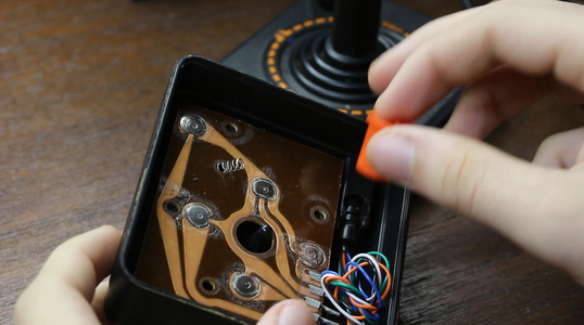

So the absolute first thing we need to do is take a look at how the Atari controller works so we can see how we are going to adapt it to USB.
So upon opening mine, I was shocked to see that it was only 5 buttons! No not 5 buttons and a control circuit, just 5 buttons. Which means adapting this to USB is going to be really easy using a microcontroller.
While I had it apart I also took some time to clean off all the gunk and give everything a good clean.
Step 2: What We Need


Now before we even get into the parts list its worth noting that this project will not work on the Arduino Uno, Nano or Mega. We need a microcontroller that can act as an HID (Human Interface Device). Microcontrollers with the ATMega 32u4 are cable of doing this and we can find an ATMega 32u4 in the Arduino Micro
Parts List:
- Arduino Pro Micro (Here)
- Male pin Headers
- USB to Micro USB cable
- Project casing (ill be 3D printing mine)
Step 3: Which Pins Do What?


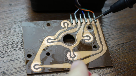
Youll see that the Atari controller has a 9 pin connector on the end of it, each button in the controller has its own pin on this connector and there's one pin for ground. That means that of this 9 pin connector only 6 pins are used. To find out which pins correspond to which buttons we can take a multimeter, set to continuity mode and see what connects. If you don't feel like going through the hassle ill include an image of my findings.
So based on this diagram we can see that for example if I were to push the fire button on the controller it would connect the orange wire to ground which is a button press, we can use our Arduino to detect this and send back keyboard commands to the computer based on which button is pressed.
Step 4: The Case


So it's been quite a long time since the last 9 pin connector has been made and because of this, it makes it quite hard for us to find one to use in our adaptor. So the solution like with most things involves 3d printing. I'm going to be printing the housing for a 9 pin connector and then ill just slide some male pin headers into it to make contact with the 9 pin connector on the Arduino. The 3d printable files can be found below.
The way we make this 9 pin connector is to first slide the male pins into the Atari 9 pin connector then slide the connector we printed over that and then final glue to back of the male pins to the back of the connector we printed. Now when we pull the connectors apart the pins should stick in the one we printed and be perfectly aligned.
Attachments

Step 5: Wiring Everything Up

So to wire everything up we need to do it as follows (remember to check which colour corresponds to which pin on the 9 pin connector) :
- The Black wire goes to Ground on the Arduino
- The Orange wire goes to pin 3 on the Arduino
- The Green wire goes to pin 4 on the Arduino
- The Brown wire goes to pin 5 on the Arduino
- The Blue wire goes to pin 6 on the Arduino
- The White wire goes to pin 7 on the Arduino
If this at all see confusing check out the wiring diagram for a little bit of clarity.
Step 6: Uploading Code
The code we are going to use can be found below. We are going to be taking advantage of the keyboard library in this code. Whats happening is we have a bunch of if statements stating that if a certain button goes low to push the corresponding keyboard key.
Now luckily the keyboard library is super easy to use, for example to code Keyboard.press(119); is stating that the keyboard key 119 (119 is ascii for W) is being pressed and the code Keyboard.release(119); is stating that keyboard key 119 is now released. So we have If statements that state if the pin is HIGH to press the key and if the pin is LOW to release the key.
We also take advantage of internal pull-up resistors in our code so we don't have to worry about soldering any into our circuit. If you'd like to know more about the code open it up in the Arduino IDE and you should see most of it is commented.
We then upload the code to the Arduino Pro Micro and move on to the next step.
Attachments

Step 7: Putting the Case Together


So the 3d printing files from the previous step not only have the 3d printable 9 pin connector but also a top and bottom piece that can fit around it and have all the circuity inclosed inside of it. So to finish up or project we need to print these two pieces.
Then we glue to Arduino down inside the bottom piece (the piece with space for a USB micro cable) then we glue to 9 pin connector down in the front of the bottom piece. Once these are both secure and in place, we can glue to the top piece on, finalizing the project! Now before I did this I actually added an excess amount of hot glue to the inside because this makes it a little stronger but also adds some weight to the device making it not feel too flimsy.
Once these pieces are all together you might notice that it looks a little rough especially if you're using a budget 3d printer like me, to fix this and get the prints looking really neat we are going to sand and then paint the outside of the case. I looked to the Atari controller and case for inspiration on the colors of my device, I decided to make one with a reddish strip and the other with some wood grain to match the Atari's body.
Step 8: Using It


So now that we've made it lets take a look at how to use it.
So first things first we want to plug our Atari controller into our adaptor, then we plug the micro USB cable into our computer and you should get a notification that you plugged a keyboard in (remember because of the keyboard library the computer thinks this is a keyboard)
Now the way the keys are mapped are as follows:
Up is W
Left is A
Right is D
Down is S
and Fire is Spacebar
So the chances are you going to have to go into your emulator and do some keybinding to make sure everything works well. This also works on Android phones if you have an OTG cable.
Thank you so much for reading, if you have any questions id be happy to answer them!

Participated in the
Game Life Contest

![Tim's Mechanical Spider Leg [LU9685-20CU]](https://content.instructables.com/FFB/5R4I/LVKZ6G6R/FFB5R4ILVKZ6G6R.png?auto=webp&crop=1.2%3A1&frame=1&width=306)


