

Introduction: Arduino Based POV Display Stick - JolliPOV Stick


Basic Arduino boards such as the Arduino Uno, Arduino Nano, and Arduino mini boards are very popular with entry-level electronics hobbyists working on electronics projects.
There are a lot of interesting Arduino based projects for makers to work on and one particular kind of projects we think are intriguing and interesting to work with are POV related projects.
Persistence Of Vision (POV), is basically an optical illusion whereby the brain is tricked to make the eye sees an “after-image” of an object for a short time after it is no longer there.
You may check out the following instructables which we have worked previously on projects employing the concept of POV.
https://www.instructables.com/id/IKEA-Frame-Hack-S...
https://www.instructables.com/id/JF-Time-Fountain/
https://www.instructables.com/id/JolliCube-an-8x8x...
In this instructable, we will set out to create an Arduino based single color multi-purpose Persistence of Vision (POV) display stick which we aptly named as jolliPOV Stick.
Most POV Sticks have an array of LEDs soldered onto the stick. Some work by waving the stick back and forth at a fast pace to see patterns or words form in mid-air with our naked eye. Some may require long exposure photo shoots in order to see more clearly the patterns or words formed by the sweeping movement of the POV Stick. POV Stick can also be mounted on motors or moving platforms for better visuals.
Our POV display stick is versatile and can work handheld by waving it or be mounted on a motor to become a rotating LED display with the display on the stick itself as well as by the side.
Experimenting with POV Stick is fun, fascinating and educational. We have designed our POV Stick to work with the popular Arduino board and is powered with a readily available 9V battery.
For this project, one needs to possess some basic soldering skill, basic electronic knowledge and is familiar with working on Arduino boards.
You may build the POV stick using Perf boards from the schematic diagram for our jolliPOV stick but we will not be showing how to build it in this instructable. The schematic diagrams for jolliPOV are available in the next section.
For those who prefer not to mess around with too much wiring, jolliPOV Stick is available as a DIY kit at https://www.tindie.com/products/Nick64/jf-jollipov-stick-diy-kit/.
You may check out the following YouTube video to see jolliPOV Stick in action;
Step 1: Design of JolliPOV


Overview
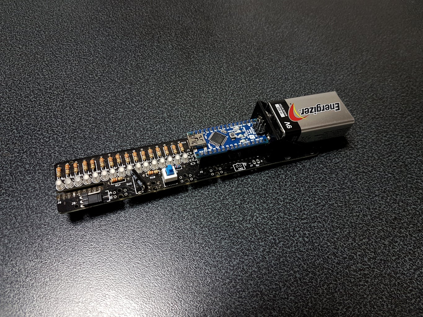
Our POV Stick is made up of the Main PCB and an Add-On PCB which can be easily plugged onto the main PCB end for side display.
We will be using single color diffused 3mm LEDs for our POV stick. It shall have an array of 16 LEDs mounted on the Main PCB. 16 LEDs, a multiple of 8, should be good to work with for program coding since a byte has 8 bits. We also designed a small Add-On PCB with an array of 8 LEDs to be easily attached to the POV stick for a side POV stick display.
An Arduino Nano board is used to drive our POV Stick. As there are not enough output pins on the Arduino Nano board to directly drive each LED, 8 of the LEDs on the Main PCB and the 8 LEDs on the Add-On PCB are driven by the same 8 output pins from the Arduino Nano board. We have designed to use a jumper for selecting if these 8 output pins are driving the LEDs on the Main or Add-On PCB. With the jumper set to position 'A', the 8 LEDs on the Add-On PCB can be driven. Otherwise, the LEDs on the Main PCB can be driven.
Synchronization
To make static graphics or words displayed from shifting position, there must be a mean to determine a 'Home' position and trigger for the start to display the graphic or word sequence. Commonly used methods employ Hall Effect sensor with a magnet, reed switch with a magnet, Infrared Red (IR) sensor with a reflective object or an object to break the IR beam, an accelerometer or a simple momentarily switch.
We used a TCRT5000 IR reflective sensor with a reflective object for 'Homing' to define the start point of one rotation if jolliPOV Stick is to be mounted onto a motor to act as a rotating display stick and an SW-200D ball tilt switch for 'Homing' if it is to be handheld and waved back and forth to form graphics or words.
The IR reflective sensor may be soldered at any of the 4 optional locations provided on the stick. For this project, we soldered it to the 2nd position from the front end but you may choose any location suitable for you.
The SW-200D ball tilt switch must be soldered with the correct polarity for it to work with our Arduino program code. If you look closely, the terminal legs are of a different color. The leg which is slightly golden in color needs to be soldered nearer to the edge of the PCB. We also recommend that it be soldered approximately 6mm above the PCB to enable it to be twisted slightly to a more suitable angle for the way you wave the stick.
Power Supply
We will be using a heavy duty 9V battery to power our POV stick as it is readily available. We will be using a separate power source to drive a suitable motor if the intention is to mount it onto a suitable motor for it to be a rotating stick display. For this project, we used a motor taken out of a 7 inch USB desktop fan which is strong enough to support and rotate our POV stick with the 9V battery mounted on it.
Balance for stability
If jolliPOV Stick were to be mounted onto a motor to act as a rotating display, it needs to be mounted as much as possible at the mid-balance point of the stick for stability. If you are using a different power source or added other modules to your POV stick such as a RTC module for display of clock information, this will change the weight and balance of the stick. There are a number of mounting holes strategically provided on the POV Stick for you to choose to mount it onto the motor shaft for best possible balance.
* NOTE: The schematic diagrams for our jolliPOV Stick Main and Add-On PCBs can be found in the images above. You may wire up your own POV Stick based on our diagrams.
Step 2: Building the POV Stick Electronic Circuit Boards


We built our prototype POV Stick using perf-boards. You may similarly do so but we will not elaborate on how to build it using perf-boards here. We have designed and come up with the Main jolliPOV Stick PCB and the Add-On PCB which will make the project look sleeker.
Parts required to build our jolliPOV Stick with the Add On PCB:
- 26 x 330 ohms Resistor
- 24 x 3mm Super Bright Diffused LED
- 2 x Phillip Countersunk Self Tap Screw
- 2 x 15 pins Single Row 2.54mm Female Straight Header
- 1 x 9 pins Single Row 2.54mm Female Straight Header
- 1 x 9 pins Single Row 2.54mm Male Angle Header
- 1 x 3 pins Single Row 2.54mm Male Angle Header
- 1 x 12K ohms Resistor
- 1 x SW200D Ball Tilt Switch
- 1 x TCRT5000 IR Sensor
- 1 x Pushbutton Latch Switch
- 1 x 2.54mm Header Short Circuit Jumper
- 1 x 9V Battery Holder
- 1 x jolliPOV Stick Main PCB
- 1 x jolliPOV Stick Add-On PCB
- 1 x Arduino Nano Board
The following are the main steps for assembly of the main PCB:
Caution: Identify the top and bottom of the PCB from the labels ‘TOP’ and ‘BOTTOM’ silk-screened on the PCB. Ensure you are on the correct side of PCB before proceeding to solder the components. All components are to be soldered to the TOP of the PCB except the TCRT5000 sensor and 9 pins Single Row Female Straight Header
Step 1: Solder 18 x 330 ohms resistors to the locations from R1 to R18.
Step 2: Solder 1 x 12K ohms resistors to location R19.
Step 3: Solder 16 x 3mm LEDs to the locations from L1 to L16 (Ensure LED polarity is correct - the longer leg is the anode and should go to the hole labeled as + at BOTTOM of PCB).
Step 4: Solder 1 x Push Button Switch to location SW1 (Ensure orientation is correct so the power is ON when the push button is depressed and latched. See photos above for orientation of push button).
Step 5: Solder 1 x SW200D Ball Tilt Switch to location SW2 ( Ensure the switch orientation is correct to work with our Arduino sketch - the brass/gold color leg should be soldered nearer to the LEDs. The switch should preferably be soldered around 6mm above the top surface of PCB to enable us to twist it off axis if there is a need).
Step 6: Solder 1 x 3 pins Single Row Male Angle Header to location J5.
Step 7: Solder 2 x 15 pins Single Row Female Straight Header to the locations J1 and J2 (Install Arduino Nano board onto the Headers before soldering for ease of soldering).
Step 8: Solder 1 x TCRT5000 IR sensor to any of the 4 sensor locations provided at BOTTOM of PCB (Ensure the polarity of the sensor is correct by matching the shape of the sensor to the outline of sensor silk-screened at BOTTOM of PCB).
Step 9: Solder 1 x 9 pins Single Row Female Straight Header to locations J6 (Ensure it is soldered to BOTTOM of PCB).
Step 10: Solder the RED and BLACK wires from the 9V Battery Holder to CN1 + and - respectively (Ensure polarity is correct).
Step 11: Secure 9V Battery Holder to TOP of PCB using the 2 x Phillip Countersunk Self Tap screws. Hide excess wires below battery holder.
Step 12: Install a 9V battery onto the Battery Holder.
The following are the main steps for assembly of the Add On PCB:
Caution: Identify the right and left of the PCB from the labels ‘RIGHT’ and ‘LEFT’ silk-screened on the PCB. Ensure you are on the correct side of PCB before proceeding to solder the components. All components are to be soldered to the RIGHT of the PCB except the 3mm LEDs.
Step 1: Solder 8 x 330 ohms resistors to the locations from R9 to R16.
Step 2: Solder 1 x 9 pins Single Row Male Straight Header to location J9.
Step 3: Solder 8 x 3mm LEDs to the locations from L9 to L16 (Ensure LEDs are soldered on LEFT side of PCB and polarity is correct - the longer leg is the anode and should go to the hole labelled as + at RIGHT of PCB).
You may check out the following YouTube video on how to assemble the electronics components onto the Main and Add On PCB board.
Step 3: POV Demo #1 - Arduino Program Code


For this demo, we will be using the POV stick to display stored text messages and graphics by waving the stick back and forth in mid-air.
It will be quite tiring after waving your POV stick for a while. Having long text messages will tire you out very soon as you have to wave to form a bigger arc. So for this demo, we recommend displaying short text messages and graphics. It is less strenuous if you wave the stick horizontally instead of vertically in mid-air.
For 'Homing' to start the display for this demo, we will be using a Ball Tilt switch on the Main PCB for the trigger. If you follow our assembly instruction closely in STEP 3, this switch is soldered around 6mm above the top surface of the main PCB to enable us to twist it off axis if there is a need to. We personally twist it anti-clockwise around 15 degrees off for it to work best with the way we wave the stick.
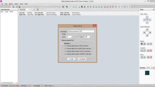
As jolliPOV have an array of 16 LEDs on it, it would be good to use a large size font for display. We searched online and found an amazing article by George Gardner showing how we can create a font from one of your computer’s TrueType fonts that’s easily scalable to any size of LED matrix.
You may check out this article which is available at http://www.georgegardner.info/arduino/easy-font-creation-for-led-matrix-from-truetype-system-fonts.html.
We created a 10X16 font for this project using George Gardner’s method. As this font file takes up a huge chunk of ram space if we were to simply load it for use in our code, it may cause our POV stick to perform erratically due to low RAM memory. RAM is precious on a microcontroller and to work around RAM issues, we will need to store the font data in program memory.
You may check out this awesome write-up by Nick Gammon on Arduino RAM utilization available at http://www.gammon.com.au/progmem.
We created some graphics which are 64 (width) X 16 (height) for display on our POV stick using a LED Matrix Editor with source code available at https://github.com/stefangordon/dotmatrixtool. This tool by default can only edit graphics with a maximum size of 32 (width) X 32 (height). We downloaded the source files and amended the index.html file to enable it to work with a maximum size of 96 (width) X 32 (height). See image above for the additional lines required for the index.html file.
The Arduino sketch for jolliPOV Demo #1 can be downloaded in the link below:
Click here to download JF jolliPOV Demo1 Ver 1.0 program files
For this demo, we have programmed it to loop through a few text messages and graphics by displaying them when jolliPOV is waved starting from left to right. A lapse of at least 800 msec is required before it can be re-triggered
to display the next text or graphic so nothing is displayed while the stick is returned to start position.
NOTE: The Header short circuit jumper at J5 need to be installed at position B for display on main PCB LEDs for this demo.
Step 4: POV Demo #2 - Arduino Program Code


For this demo, we will be using the POV stick to display stored text messages as well as repeat patterns and graphics on the main jolliPOV Stick by mounting it onto a suitable motor to make a rotating LED display. For "homing" of our text and graphics display, we placed a white eraser strategically to reflect the IR signal from the TCRT500 sensor back to detect the start of each rotation.
We created some patterns 8 (Width) X 16 (Height) which shall be repeated and some graphics 96 (Width) X 16 (Height) for display on our POV stick using a LED Matrix Editor with source code available at https://github.com/stefangordon/dotmatrixtool.
This tool by default can only select to work on graphics with a maximum size of 32 (Width) X 32 (Height). We have customized the DotMatrixTool to allow selection for a width of 96 to create larger graphics of Width 96 x Height 16. This is easily done by modifying the index.html file downloaded to add more width selection options. See photo above on the additional lines to be added in the file. We can launch this DotMatrixTool by opening the index.html with our favorite web browser.
The Arduino sketch for jolliPOV Demo #2 can be downloaded in the link below:
Click here to download JF JolliPOV Demo2 Ver 1.0 program files
NOTE: The Header short circuit jumper at J5 need to be installed at position B for display on main PCB LEDs for this demo.
Step 5: POV Demo #3 - Arduino Program Code


For this demo, we will be using the POV stick to display stored text messages as well as graphics by the side of the rotating stick. The main PCB is mounted onto a suitable motor and the Add-On small PCB with an array of 8 LEDs is attached to the main jolliPOV Stick for the side display. We created some graphics which are 8 (Width) X 8 (Height) for display on our POV stick using an online LED Matrix Editor instead of the editor we are using for Demo #1 and #2 which is available at
https://xantorohara.github.io/led-matrix-editor/....
With the Add-On PCB attached to the main PCB, the rotational speed is reduced by around 15% with the motor we used for this project. For "homing" of our text and graphics display, we placed a white eraser strategically to reflect the IR signal from the TCRT500 sensor back to detect the start of each rotation.
The Arduino sketch for JF jolliPOV Demo #3 can be downloaded in the link below:
Click here to download JF JolliPOV Demo3 Ver 1.0 program files
NOTE: The Header short circuit jumper at J5 need to be installed at position A for display on Add-On PCB LEDs for this demo.
Step 6: What's Next?


We used a 7 inch USB desktop fan motor to build our rotating POV display. The motor is good but not powerful enough to rotate our POV stick at a higher rotational velocity for a much better visual effect. You may use a more powerful motor for your project but take good care not to get hurt by the rotating POV stick.
We think a simple POV stick is a good and interesting gadget for experimenting with the Arduino board. The 3 demos provided here will hopefully kick start your interest to work with the Arduino board and into coding. There are more things you can do with the jolliPOV stick. Get started and see what you can do with the jolliPOV Stick.

Participated in the
Arduino Contest 2019


