

Introduction: Arduino Cyclone Game


This is a great project for the beginner(in fact it was my first!) I have no background in electronics knowledge, but found that this project was great for touching on digital outputs, analog outputs, push button inputs, and the value of resistors(due to a few surprising pops). I do luckily have a year of AP CompSci under my belt which helped out a ton for my entry into the wonderful world of Arduino.
The game is similar to a "Cyclone" at an arcade in which a light moves rapidly around a circle and to win you have to press a button when it's in the "jackpot" spot. This game works with a line of 6 LEDs and is in the considered in the "jackpot" position on a certain one.
This project came about through my beginner level tinkering. It is unfinished and nothing is soldered, but I can imagine this being a really fun toy for a kid in a finished model. I would love constructive criticism and some insightful tips about my electronics.
Step 1: LED Assembly


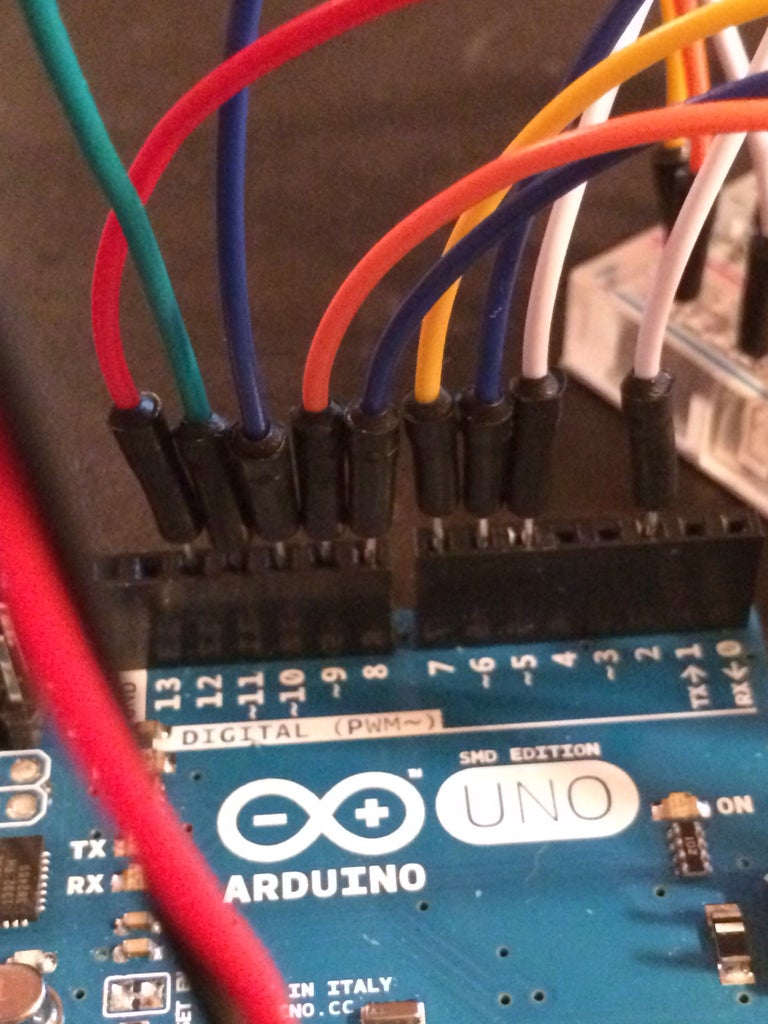
In this project I used 6 LEDs (Basically tiny light bulbs) to provide the visuals for the game. I arranged them red, red, green, green, blue, blue. LEDs, however, can blow if they're overloaded with power. As a result, LEDs need to be in line with resistors. On my breadboard, I gave every wire from an LED output pin two numbered rows. One is for the incoming current (J) to be paired with one leg of a 220 ohm resistor (I) (labeled red, red, brown). The second row is for the other leg of the resistor(F of the next row) to be paired with the wire(J of that same row) that then runs to the anode(long leg) of the LED. The cathode(short leg) of the LED then must be grounded. It is advantageous to wire the column of your breadboard labeled negative to the ground on your Arduino so that you can use it for each element of the game. I enjoyed the aesthetics of the six parallel resistors and it kept my tiny board organized. On the end with the actual LEDs I found it easiest to put all of the cathodes in one numbered row (23) so they could share a ground. Each anode needs it's own row so I bent the anodes to reach each of the three rows above the cathode row. It doesn't look great unfiddled with but with a little more bending the LEDs can be in a perfect line. I can't imagine that my arrangement is the most efficient, but the resulting brightness and performance of the LEDs was acceptable and balanced.
As you can see in one of the pictures I used a majority of one row of I/O pins.
Step 2: The Push Button
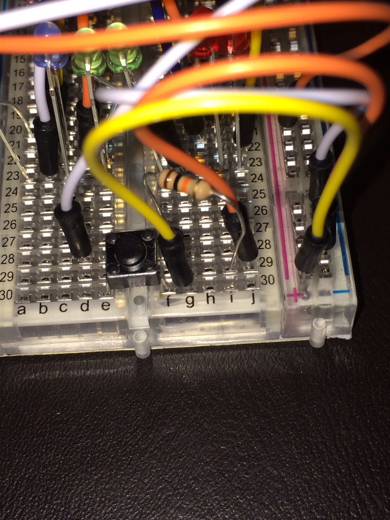
The momentary push button is an interesting section mainly for its fun coding. The wiring is accomplished by a digital pin run to one leg of the button(28D) across from a ground with a resistor (28F, 29I, 29J) and opposite from a 5v power supply(30F).
Step 3: The Happy Bell Servo


I enjoyed this part a lot. Basically, I wired up a hobby servo from an old RC airplane and connected bells to it to jingle. When a player wins the game there's movement, lights and sound which made me pretty happy. The well finished breadboard intended wires fit nicely into a servo end, but I'm sure this could be accomplished with some tactful taping or even a soldering gun(if you want to keep the game) I wired the black servo wire to the ground, the red to a 5v power supply, and the white to an ANALOG output pin on the Arduino(analog is capitalized because for a while I hadn't realized that I was trying to analogWrite to a digital pin). Analog is noted on your Arduino with a ~ next to the number. I then twisty tied some jingles to a skewer and taped the skewer to the servo arm. It's that simple!
Step 4: The Buzzer
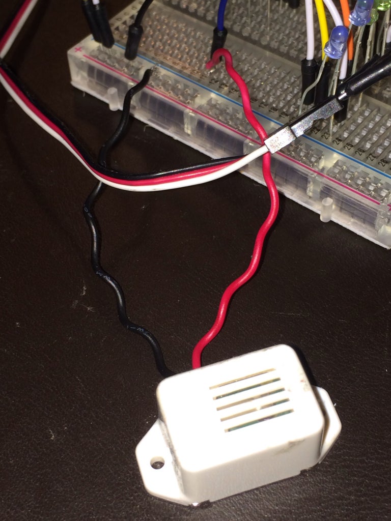
I had an old buzzer left over from a morse code unit I built with my friend a while back. I used the buzzer as another celebration output for a victory. It kind of over rode the sound of the jingling servo, but the more the merrier so on comes the buzzer. I wired it just like an LED but without a resistor. My buzzer doesn't play different tones(to my knowledge) and therefore ran perfectly with a digital output. For the beginners out there, digital is different from analog in the fact that it is always either on or off (HIGH or LOW comparable to a Boolean in Java) whereas analog can be written with a multitude of values that certainly exceed my present knowledge.
Step 5: The Coding


Here's the part that puts all of this together. I know that I'm guilty of a little bit of gauche hard coding, but hey I'm a little rusty on coding. I start off with a #include which tells the sketch program that I will be using the servo library. The servo library makes it easy to control the output of the servo. Next I initiate a servo object named "myservo". I then created integers to store the output pin values for each element in a comprehensible way. They appear in a jacked up order because of my wreckless wiring habits. Each led is given a number value based on its position in the line. I know that it may be confusing to use the English value of a number, but trust me, it helped a ton later in the code. I also instantiated integer variables lightNum, dir, state, and lastLoop.
In the setup the coder needs establish the intention of each used pin. The myservo has a method for this while for all of the others you can use pinMode.
The loop is where the action begins.
The most important variable in this program is arguably the lightNum variable. Each time the main loop repeats, lightNum has a different value between -1 and 5. This is achieved by the += assignment with dir. The variable dir is always assigned either 1 or -1 so by += with lightNum the value of light num is either added to by one or subtracted from by 1. Dir is 1 while ascending and -1 while descending. The value of dir is assigned near the end of the code where it checks, in two if statements, if lightNum is at it's max or min(and needs to be turned around)
To determine how lightNum affects the LEDs I wrote a simple system of if statements. If lightNum is >= the LED then it is illuminated(by calling digitalWrite(). I probably could've used a switch statement, but I decided I'd leave that relearning for another day.
Determining the input of the user was somewhat tricky, but interesting to me. The coding has to account for the possibility that a player could just hold the button down to win(cheaters). I remedied this by coding a variable called "lastLoop" that ensured the button had not been held. If the button had not been pressed during the last go round then "lastLoop" = LOW. Otherwise it's HIGH. So therefore if lastLoop is LOW and buttonState is HIGH then this is the all important first time press and a valid press to win. If it is valid then a variable "first" is assigned HIGH.
Determining if the player is a winner was done by a simple if statement. If this is a singular press (first == HIGH) and lightNum is desired (in my case lightNum == 5) then the system can start it's celebration.
I began by giving the servo a centered value. It will be 1500 I believe for most servos. The max and min values, I believe, can differ. I only wanted I to wiggle so in the celebration "for" loop I have it values alternating between 1300 and 1700. The servo is controlled using the myservo.writeMicroseconds() statement.
Also controlled in the for loop is an alternating led flash (3 and 3) as well as a buzz from the buzzer. Writing to digital pins is easy by just calling digitalWrite(the number of the pin, the desired value of the pin)
I delayed the loop to make it run in a timely manner. To make the game a little bit harder I made the delay on the winning lightNum value shorter than the rest.
Step 6: Play!
My little sister loved the project and quickly became an Arduino Cyclone master. I personally really just enjoyed learning about all the things that made it tick. I hope that it can put a smile on some of y'all's faces too.

Participated in the
Game.Life 4 Contest

Participated in the
123D Circuits Contest


