

Introduction: Arduino Display Matrix (32 X 8 DOTS)


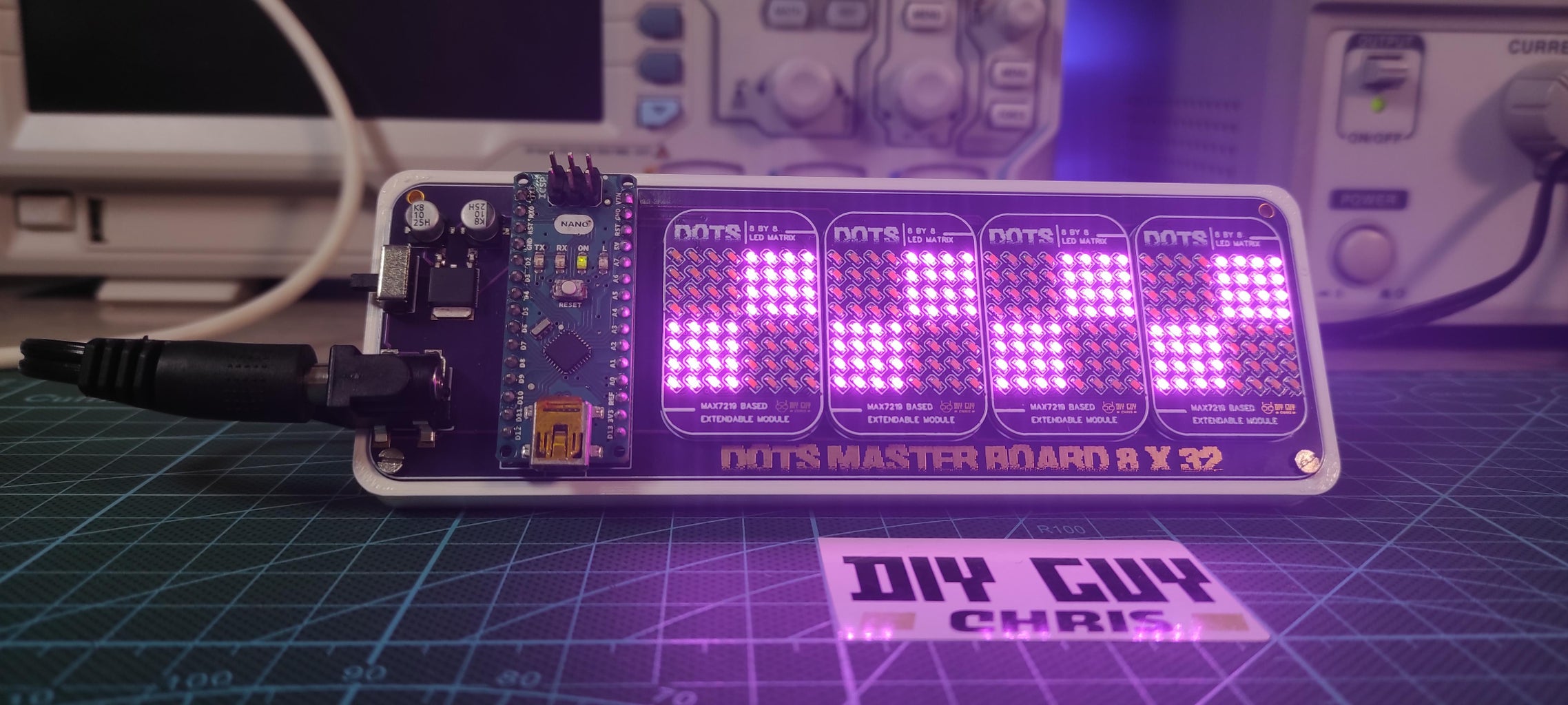
Today, I'm thrilled to guide you through the steps to create your very own 32x8 compact LED matrix, driven by an Arduino Nano.
For a double fun, the used LEDs are purple. Let's dive right into it!
Supplies


What You'll Need:
Ingredients
- Arduino Nano
- MAX7219 LED driver circuit
- 8x8 LEDs (4 matrices)
- 256 SMD LED of package size 0603
- Mezzanine connectors
- 7805 SMD voltage regulator
- Host board (Arduino Nano & LED matrices)
- Power Jack connector
- On/Off switch button
- Two SMD electrolytic capacitor 10UF 25V
- Altium Designer for board designs
Tools
- PCB Stencil
- Soldering Hot-Plate MHP30
- Solder Paste
- Tweezers
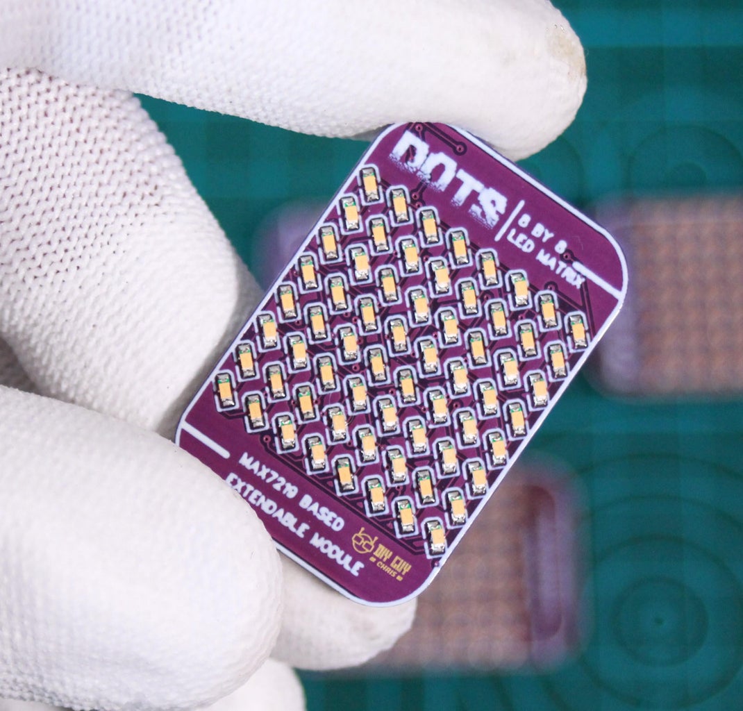
Step 1: Designing the LED Matrix
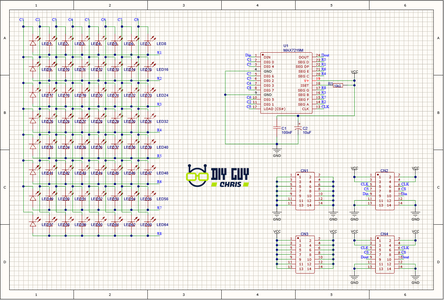


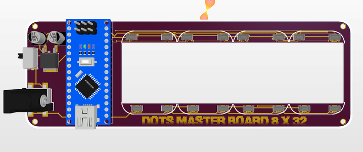
The gadget is built around two main circuit boards, the LED Matrix and the Host master board.
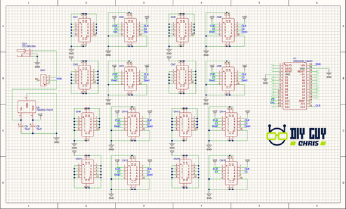
In a previous project, I shared the making details of an 8x8 LED matrix. For this project, I expanded the display by assembling four of these matrices. Using Altium Designer, I created a host board to connect the Arduino Nano and LED matrices via mezzanine connectors.
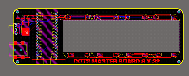
Step 2: Board Fabrication
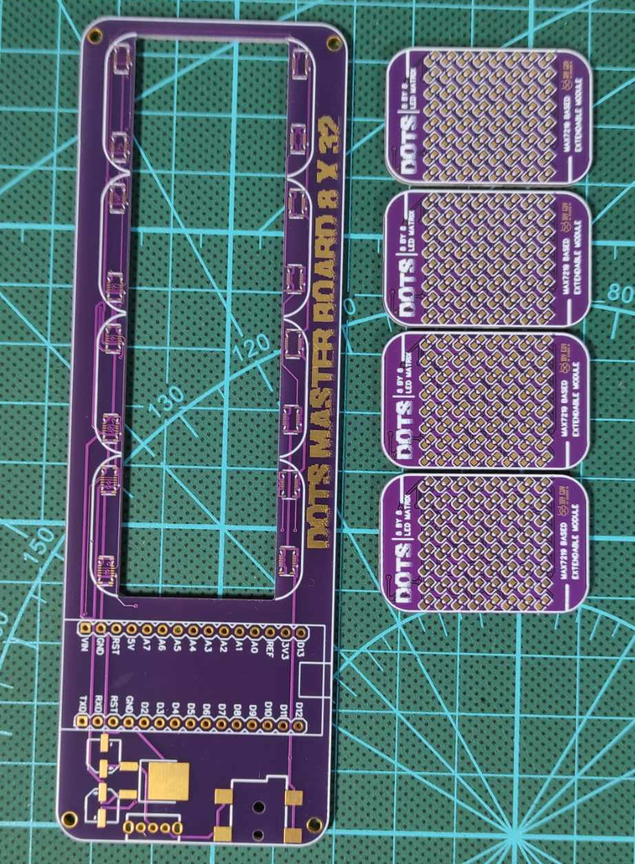
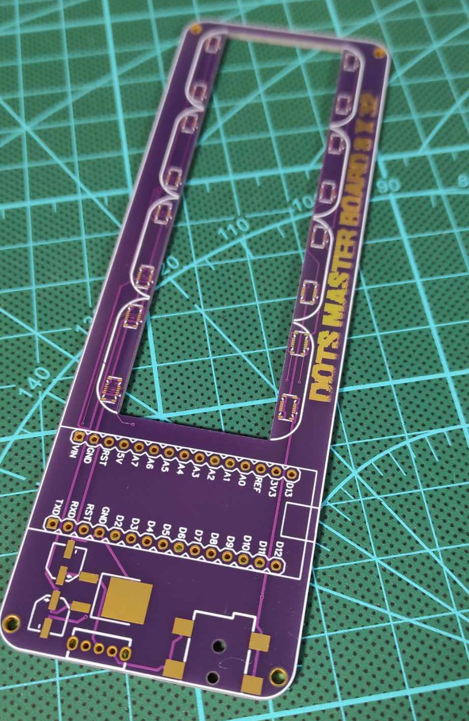
After designing the boards, I generated GERBER Files and placed an order with JLCPCB. In just 6 days, the boards arrived. I opted for a Purple PCB color, ordering 10 pieces of the matrices to produce multiple LED Displays.
I Already have the PCB stencil that I ordered for my previous design so no need to ordered it again here.
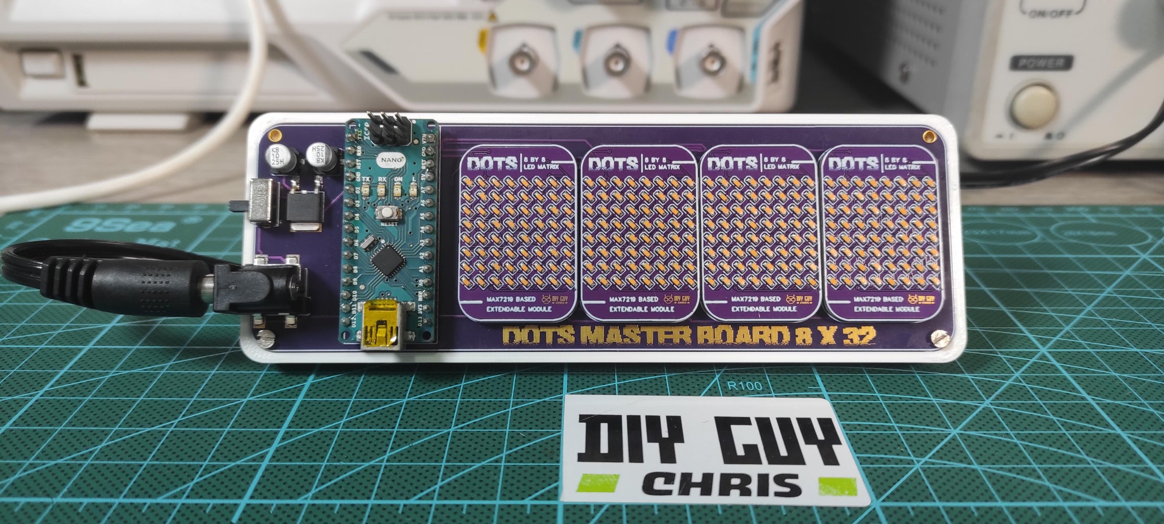
Step 3: Board Assembly
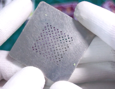


Utilizing a previously ordered PCB stencil and following the same LED arrangement, I assembled the matrices. Soldering the MAX7219 integrated circuit and male mezzanine connectors completed the process for each matrix.
Moving to the host board, I soldered the surface mount devices, including female mezzanine connectors for board connectivity. The Arduino Nano was then soldered onto the host board, connecting to designated pins for Clock, Data, and Chip Select.
Step 4: Testing and Code Execution
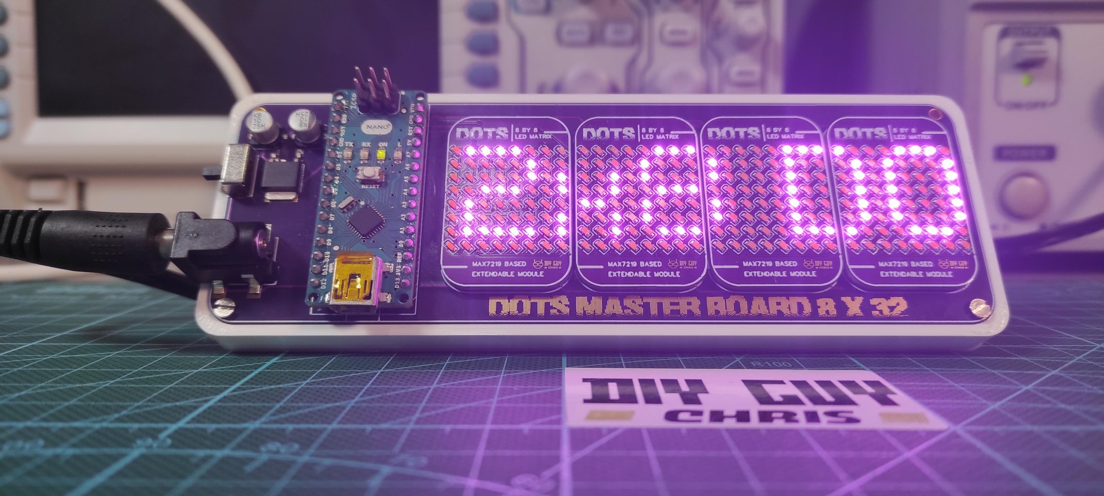
Referring back to the circuit schematic, I designated digital pins on the Arduino for Clock, Data, and Chip Select. The host board's connections and common pins ensured proper communication between the matrices and Arduino.
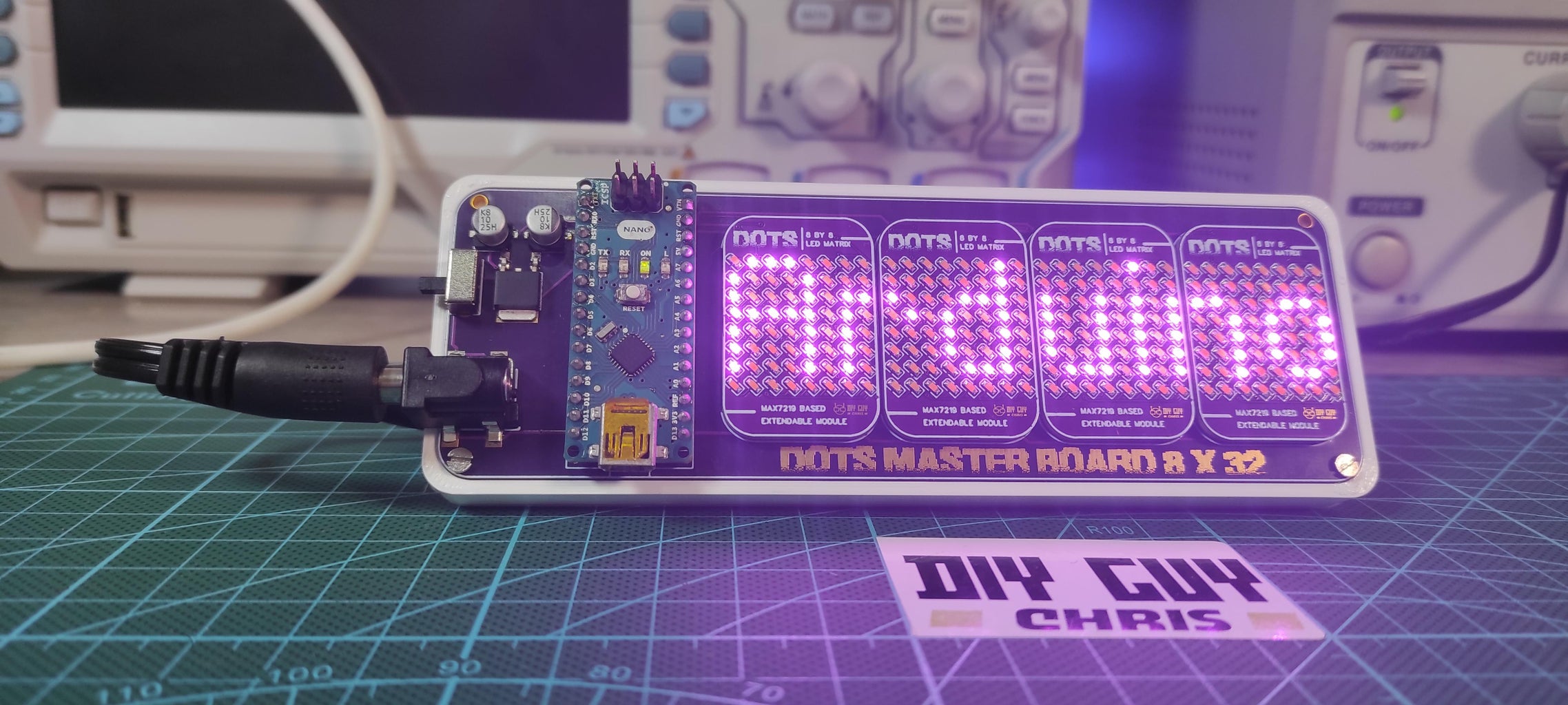
Using an Arduino library (MD_MAX72xx.h), I uploaded a test code to verify the hardware. The LEDs lit up beautifully, displaying coded animations flawlessly, confirming the success of the circuit.
Conclusion
Building this LED matrix has been a delightful journey! I'm always open to improvement ideas, so feel free to share your thoughts in the comments section below.
Remember, engaging with electronics regularly enhances your skills. Thanks for joining me today. This is Chris signing off—see you in the next tutorial!

Participated in the
Anything Goes Contest


