

Introduction: Arduino Home Monitor System


Greetings!
In this Instructable, I will detail how I made my own homebrew home security system based on Arduino. I will admit, it's not the most secure in it's current state, but given certain modifications and higher grade components along with tweaking of the code, it could prove to be a formidable system.
There are many different aspects to the Arduino program that you will most assuredly learn along the way, such as switches, debouncing, LCD displays, and a few more. This guide will show you how I myself went about the process (and I am always open to comments, questions, and criticism!).
Let's begin!
Step 1: Requisites
First of all, I will assume one has a basic to intermediate level of understanding of the following -
-Arduino - writing sketches, using the IDE, etc.
-Some basic soldering skills (I'll admit, I am surely not the best!)
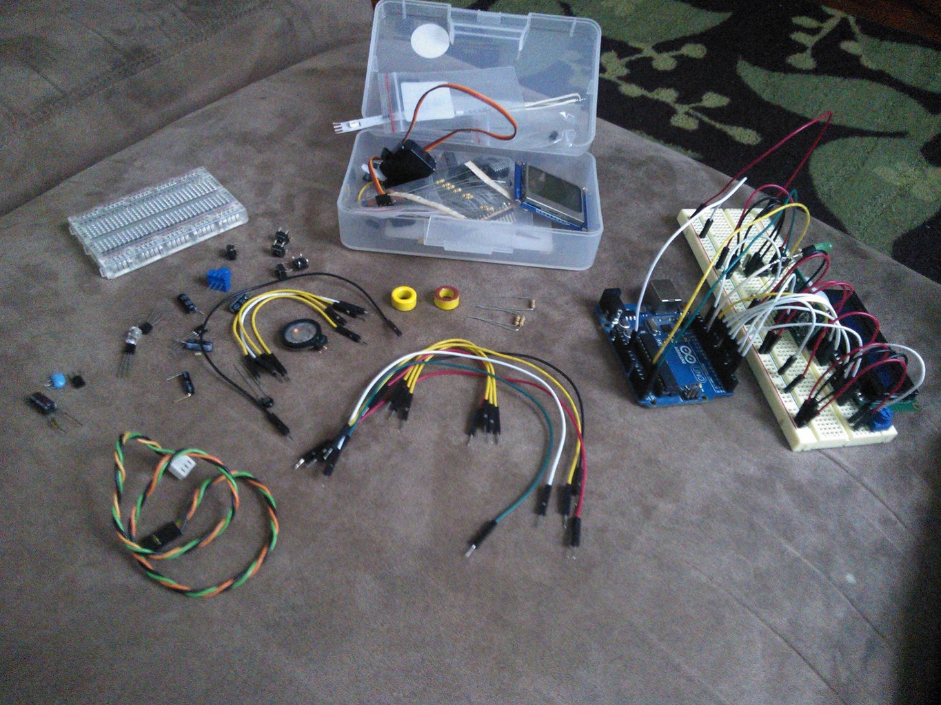
-For this particular Instructable, you will need (or might need) -
-Arduino Uno
-16x2 LCD Display
-10k Potentiometer
-Magnetic Reed Switch (also a magnet)
-PIR Motion Sensor
-DS1307 Real Time Clock
-32.768kHz Crystal
-3V Coin Cell Battery
-5v Regulator (LM7805)
-10uF Electrolytic Capacitor x2
-10k Resistor x3
-Piezo Speaker
-LED (I used a superbright white LED)
-Iron Ferrite Choke
-A generous length of CAT5 cable
-A breadboard or two.
-Soldering Iron
-Solder (of course)
-a bunch of jumper wire (the more the merrier!)
-any spare female wiring you can get your hands on. I have a bunch of computer parts, so for me, this is in no short supply!
(Please forgive the messyness of my parts bin! :P)
Step 2: Scoping the Place Out...


First you want to identify points of entry that you want to be monitored.
For this project, I only have two areas I am monitoring - the walkway leading up to my house, and the door to my garage. If you prefer your sensors to be inconspicuous, be sure to have them in a well hidden spot, but also a place that does not interfere with functionality. I live above my garage, so there are stairs leading up to my front door. I tucked my PIR right under the edge of my porch, facing the walkway. Hard to see (except at night when it's triggered. At that point, the little red glow already says it's too late :P).
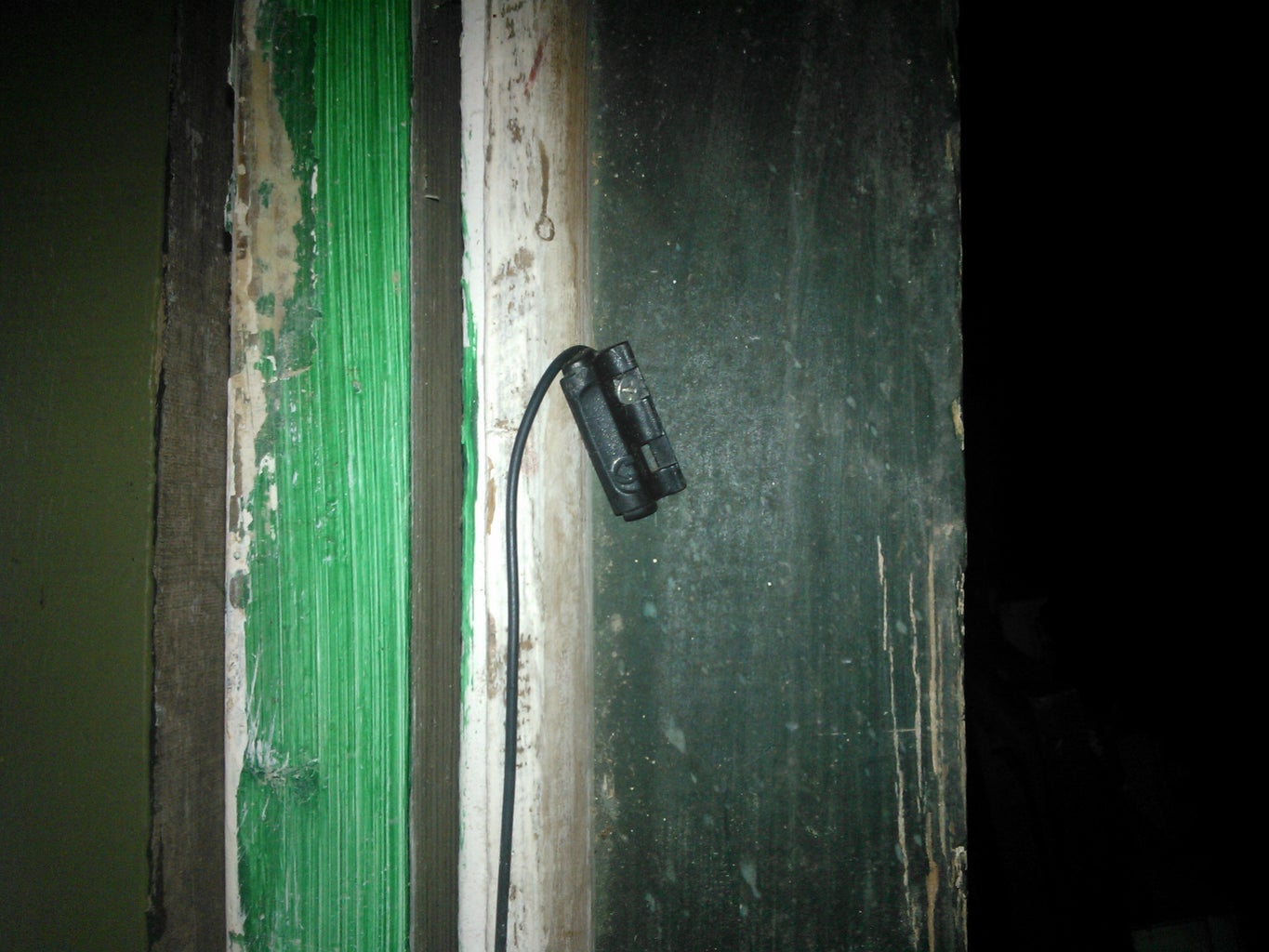
The reed switch is placed on the inside right on the door frame, with the magnet on the door, so that when the door is closed, they are right next to eachother and can do their job.
You'll want to measure out how much of that CAT5 cable you'll need. If you managed to wrangle up some female wiring, you can use that to connect the sensors to the cable. Once that is out of the way, we can start putting things together on the breadboard.
**NOTE - jot down the wires you used to connect the sensors, ie, the orange/white wire is connected to ground on the PIR, blue/white to VDD, green/white to signal. You definitely don't want to get those mixed up!**
Step 3: Wiring It Up - Magnetic Reed Switch!

Now we can start putting things together to test out the system (or if you're like me, you're usually satisfied with the breadboard setup and will consider the project complete after this step lol).
Here is where we start assigning the pins on the Arduino. If you're not familiar with using some of these items, I'll try to detail them as I go, but just as well, there is a plentiful amount of tutorials specifically tailored for most of these items. For example - if you havent used a 16x2 LCD display with an Arduino, Lady Ada has a great lcd tutorial here - http://learn.adafruit.com/character-lcds/overview - that's where I learned! And as well, Google will be your best friend for finding tutorials.
At any rate, I will detail each item as we go. Let's start with the magnetic reed switch.
We will assign this one to pin 3 of the Arduino . As the picture shows, we want to hold the digital input either low or high (depending on how you want it to be triggered) with the 10k resistor. Otherwise, the Arduino may sense intereference and interpret that as the switch being tripped. No bueno.
The Arduino IDE also has some examples with buttons (which work the same) if one needs practice or introduction.
Step 4: Wiring It Up - PIR Motion Sensor!


Here we have the PIR Motion Sensor (PIR = Passive InfraRed).
It's a simple little device that signals when motion is detected. When there is motion, the signal line goes high, whereas it's low when all is quiet. Integrating a PIR is quite simple. It's practically the same concept as buttons, but instead of physically pushing a button, the PIR switches it's output accordingly (LOW or HIGH) when there is or is not motion present.
We will attach it's signal pin to Digital Pin 2 of the Arduino. Quick and easy setup!
Step 5: Wiring It Up - 16x2 LCD Display!


This one is a little more complicated, but not by much.
The link in Step 2 directs you to Lady Ada's tutorial on LCD Displays. There she covers the wiring and code to get your LCD up and running! For this project, we will be using Digital Pins 5, 6, 7, 9, 10, and 11 of the Arduino. The picture shows the corresponding connections as there are 6 between the LCD and Arduino.
We will use the display to show the status of the sensors, and to show the time when the system is idle (no "intrusions" detected).
Step 6: Wiring It Up - DS1307 Real Time Clock!


We will be using the DS1307 to basically just keep time. I plan to implement a sensor log to store events, ie, whenever a sensor is tripped, it will log the date and time and which sensor. That is for another instructable (as I have yet to tinker with data logging!) and also utilizes an SD shield (or ethernet shield!) for the Arduino.
For this, we will be using the Data and CLock lines on the Arduino (A4 = Data, A5 = Clock). The DS1307 is an I2C device, so some basic knowledge of I2C would most definitely be useful (again, plenty of tutorials online!). Connect the corresponding Clock and Data lines. The 32.768kHz crystal goes on pins 1 and 2 of the RTC. Pin 3 is for the coin cell battery, but if you're just using the breadboard, connect this pin to ground for proper operation. Pin 8 is 5v, and pin 4 is ground. Pin 7 is a Square Wave ouput, that which I have also yet to tinker with.
We will also need pull-up resistors for the Data and Clock line since they are both open drain.
Step 7: Wiring It Up - Piezo Speaker and LED

This will be a short step.
We will create a visual and aural indication of when a sensor is tripped. Connect the positive lead of the piezo to pin 8, and the negative lead to ground. That's pretty much all there is to that one! Most of it's utilization is in the code. For a piezo (or small speaker, in my case) "tone" and "noTone" is used. If you wanted to play a short tonal pulse, one could code it like this -
void tonal(){
tone(8, 300);
delay(500);
noTone(8);
}
Quite simple. When you wanted to make a call to that function, simply put tonal(); wherever you wanted it to happen. You could also achieve the same without using void, just use the tone and noTone.
We will connect the LED to pin 12 of the Arduino. Even easier!
Step 8: Coding It Up


I have posted a link to my github if you just want to copy the sketch and disect it yourself. One thing to keep in mind - I have always found it best to connect everything up where I like it, double check all my connections (make sure you have nothing connected backwards), and then proceed to writing the code. If you still find that something is not quite working, or are having trouble integrating different aspects of a project, work with each one individually. Narrow it down. Start with the most difficult part first. For me, I always start (even with wiring) with the LCD, and work my way down to say, the LED. Hence why I had different segments of the sketch throughout this instructable!
You might wonder what the two chokes were for. When using a significant length of cable (like the CAT5 cable) there may some interference. I had this wired up once before, and the lengthy cable acted as sort of a sensor itself, picking up stray EMI (electromagnetic interference). The igniter on my stove would set off the system, as would closing and opening my microwave door! These both created sparks, which in turn cause interference and set off the system. Fun stuff! Took me ages to figure out what was going on!
You also may realize that some of the materials listed I did not use. I left those out mainly because I cannot find the PCB I got specifically for this project, and my nearest Radio Shack is not very "near", so once I find it (or am in the neighborhood), I will amend this tutorial with the final result of the project!
https://github.com/gtrstitch/home_security.git
Step 9: Credits


There are many resources and tutorials available to you at your disposal! I often defer to -
http://www.adafruit.com
http://www.ladyada.net
http://www.arduino.cc
and
http://www.google.com
If you are having trouble with your project or have any questions or comments, please feel free to let me know!
~~This Instructable brought to you by Gtr_Stitch~~

Participated in the
Arduino Contest


