

Introduction: Arduino Keyboard Piano With 8 Bit R2R DAC


I used an Arduino to generate sin waves of the appropriate frequency which are then triggered by the keypad.
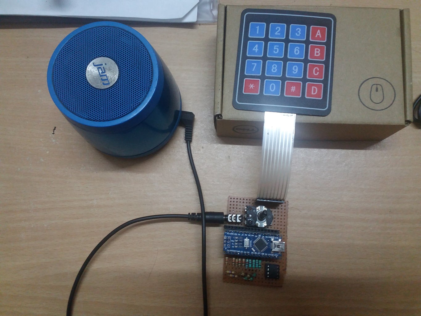
This project uses an external speaker to play the tones. The arduino sends audio data via AUX cable.
Features-
- Plays the basic notes SA, RE, GA, MA, PA, DHA, NI, SA, as well as the komal and teevra notes re, ga, teevra ma, dha and a note of the next octave for total 13 distinct notes.
- A test button which plays all these notes in succession when pressed.
- A record feature: Press this button to begin recording. The led attached to pin 13 will blink while it records.
- Play feature: Play the recorded sound.
Step 1: Music
Their are 12 notes in an octave:
Sa 240, re 256, Re 270, ga 288, Ga 300, ma 320, Ma 337.5, Pa 360, dha 384, Dha 400, ni 432, N 450. The Sa of the next octave (Sa') will have a frequency of 480 Hz.
For more details, click here.
If we have a sin wave of a given frequency, say Sa, we can produce the Sa of the next or previous octave using the same sin wave by just scaling the time by half and double respectively. This can be done by increasing or decreasing the interrupt frequency in the code.
In the code, I have used a lookup table of each of the 13 frequencies (12 in an octave plus an extra Sa) to play the sound. I generated the table with an arduino code which printed the table to the serial monitor.
Here is the code if you are interested.
Attachments

Step 2: Components
- Arduino nano
- 1k resistors: 9 nos.
- 470 ohm resistors: 7 nos.
- 10k Potentiometer.
- LM358 opamp IC
- 3.5 mm audio jack
- 8×1 Male headers for keypad.
- 15×1 Female headers for Nano: 2 nos.
- AUX cable.
- External speaker.
Step 3: Circuit
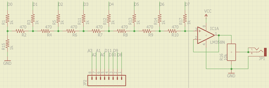
The arduino is a digital circuit, so to produce an analog sound wave we need a digital to analog converter, or DAC. An R2R ladder is the simplest dac available. The DAC has 8 digital inputs, whish is connected to PORTD of the arduino. Know more about it here.
Then I used an opamp buffer to buffer the signal so that i could control the volume with the potentiometer. Skip this part if you are fine without volume control through pot. You can do it in the code too, but this is simpler. The wire then connects to both the signal pins of a 3.5 mm audio jack.
I connected the keypad with the male headers. The row pins connect to PORTC and the column pins connect to PORTB.
OPTIONAL: You can add a red led with a 220 ohm resistor to pin 13, so that you can clearly see when the arduino is recording.
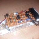
Step 4: Prototyping and Fabrication
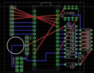
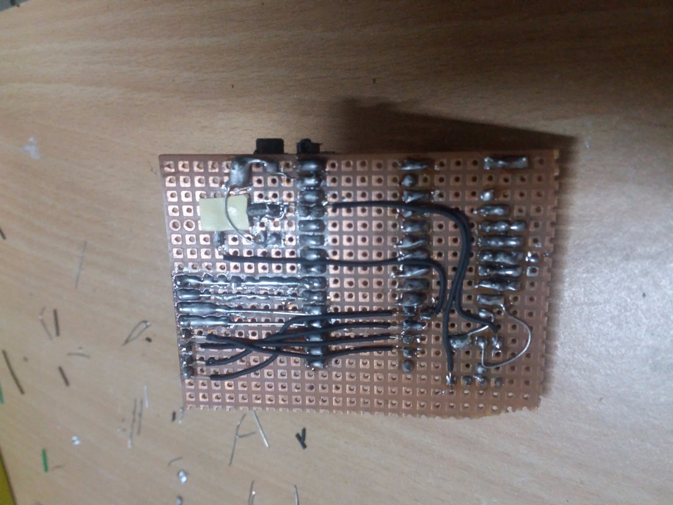
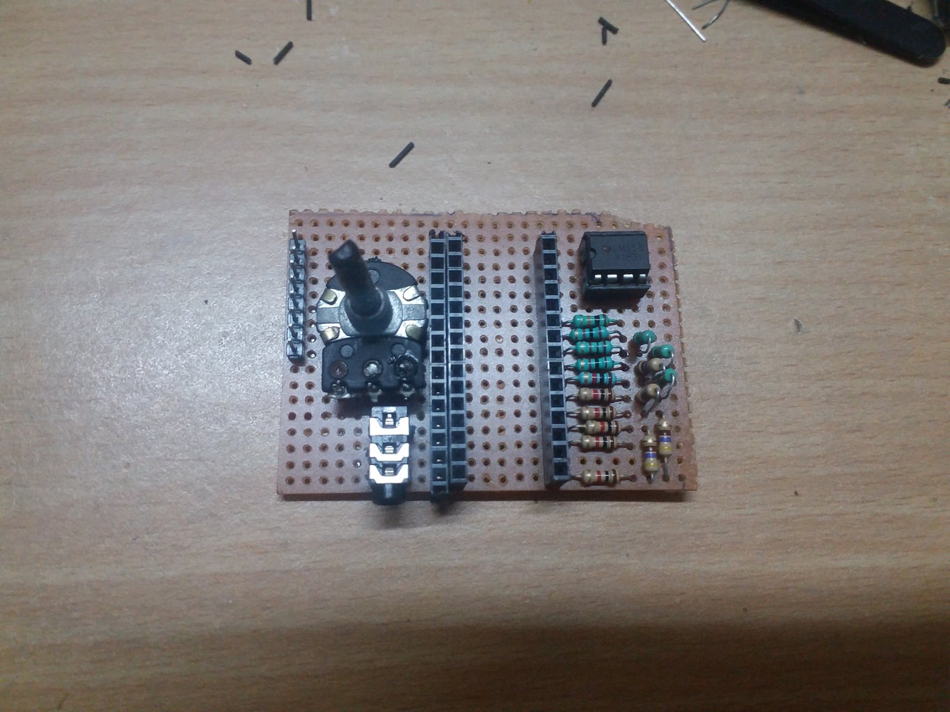
I tested the circuit in a breadboard. When everything worked fine, I soldered them on a perfboard with a little help from EAGLE. Here's a rough layout of the board.
Step 5: Code
This is the most important step.
As I mentioned before, I generated lookup tables to read the sin values. I stored these tables in the programme memory, instead of as a global variable, as that has more space.
I play the required tone by writing a byte of sin sample to the DAC every 25 microseconds with a timer interrupt.
If these interrupts are instead called every 12.5 us, all the sounds will have double the pitch. Similarly, if they are called every 50 us, we get half the pitch.
To scan the keypad, I again used port manipulation. Here is the key map i have used for the keyboard as i felt this is most natural. You are at liberty to change it by changing the key array in the code.
re, ga, ma, dha
SA, RE, GA, MA
PA, DHA, NI, SA'
RECORD, PLAY, ni, TEST


