

Introduction: Arduino - MPU6050 GY521 - 6 Axis Accelerometer + Gyro (3D Simulation With Processing)
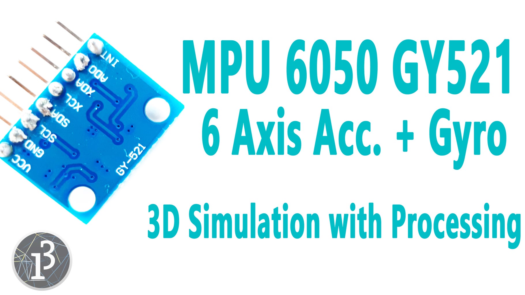


* In this tutorial we will learn how to use MPU6050 6 Axis Accelerometer + Gyro module and GY 521 breakout boards.
* Also we will install the necessary libraries to Arduino IDE.
* And last, we would run the simple simulation with this module using the Processing.
* We can make Quadcopter Drone, RC Plane and Robotic projects using with the MPU6050 module.
Step 1: Required Hardware
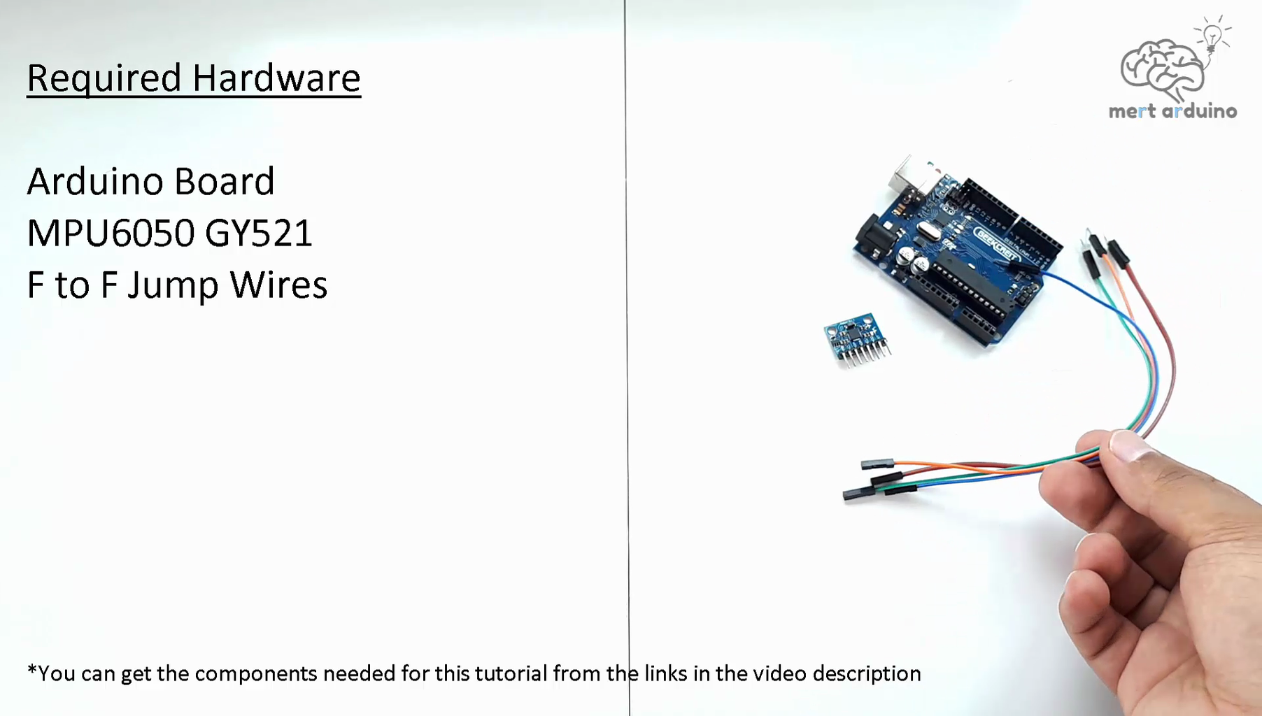
Required Hardware
Arduino Board -- https://goo.gl/Rqc5w2
MPU6050 GY521 -- https://goo.gl/wdjSo1
F to F Jump Wires -- https://goo.gl/TdGrkk
Some Promotion Links
Flash Deals -- https://goo.gl/CVqg7P
Mega Stock Clearance -- https://goo.gl/eCbuiP
Arduino Kits -- https://goo.gl/uwr19e
More Budget 3D Printers -- https://goo.gl/uwr19e
Anet A8 3D Printer Promotion -- https://goo.gl/uwr19e
Step 2: About MPU6050 Breakout Board GY-521

* The MPU-6050 sensor contains accelerometer and gyro in a single chip.
* The module captures the x, y, and z channel at the same time.
* The sensor uses the I2C-bus to interface with the Arduino.
* GY-521 modules has a voltage regulator.
* Some GY-521 modules have the wrong capacitor (or a bad capacitor) and that results into a high noise level
* In this module I bought, I did not encounter any problems.
* For more information about possible problems, http://forum.arduino.cc/index.php?topic=394691.0
Step 3: Connections

* The MPU6050 communicates with the Arduino through the I2C protocol
* The MPU6050 is connected to the Arduino as shown in the following diagram
* Connect the Arduino digital 2 input to the pin labeled as INT on the MPU6050.
* Then we need to set up the I2C lines. Connect the pin labeled SDA on the MPU6050 to the Arduino analog 4 (SDA) input and the pin labeled as SCL on the MPU6050 to the Arduino analog 5 (SCL) input
Step 4: Install I2Cdev & MPU6050 Libraries


* Jeff Rowberg wrote some Arduino libraries to obtain the accelerometer / gyro data and handle all the calculations
* We need only I2Cdev & MPU6050 Libraries for this tutorial
* https://github.com/jrowberg/i2cdevlib/zipball/mast...
* First unzip the .rar file, find the Arduino folder within it and copy the two folders "I2Cdev" and "MPU6050"
* Paste to your Arduino "libraries" folder in the following directory C:\Users\YourName\Documents\Arduino\libraries
Step 5: Uploading the Code and Testing the MPU6050


* Then open the Arduino IDE and in the examples section, you can find MPU6050_DMP6 within MPU6050
File –> Examples –> MPU6050 –> Examples –> MPU6050_DMP6
* Plug your Arduino Board to your PC
* You should set the baud rate of 115200 for Serial Monitor
* Select the appropriate COM Port and upload the sketch
* Open the Serial Monitor and set the baud rate of 115200
* Now, you’ll see a line saying “Send any character to begin DMP programming and demo.” Just type in any character on the serial monitor and send it
* And you should start seeing the yaw, pitch, and roll values coming in from the MPU 6050
* Also, you will need to wait about 10 secs before you get accurate values from the MPU6050. After which, the values will begin to stabilize.
Step 6: Show the MPU6050 Values As 3D Simulation Using the Processing Software


* To simulation the 3D model in processing, you need to comment the line in the Arduino MPU6050_DMP6 code which says
* #define OUTPUT_READABLE_YAWPITCHROLL by //#define OUTPUT_READABLE_YAWPITCHROLL
* And uncomment the line which says
* //#define OUTPUT_TEAPOT by #define OUTPUT_TEAPOT
* Select "save as" and choose where you want to save the modified code
* Then upload it again to the Arduino
* To show the 3D simulation of the data from the MPU6050, you need to install the Processing software, you can find download link in the video description. https://processing.org/download/?processing
* Processing is similar to Arduino, except for a couple of functions. Processing is mainly used for visualizing data.
* For more about the Processing, you can watch the tutorial below
* After installing the Processing IDE, we will need to download a library called 'ToxicLib'. This library is necessary for our the MPU6050 processing example.
* The latest version of the ToxicLibs library is here: https://bitbucket.org/postspectacular/toxiclibs/d...
* Unzip ToxicLibs and place all the contents to the processing folder (yourProcessingFolder - > modes -> java -> libraries)
* Last of all, open the Processing Software
* Next, you have to open the Processing example for the MPU6050
* Open the folder where you added the MPU6050 library for the Arduino
(MPU6050 -> Examples -> MPU6050_DMP6 -> Processing -> MPUTeapot)
* Click the RUN button and the system should calibrate for about 10 seconds
* Then you can test the yaw / pitch / roll of the MPU6050
Step 7: You Can Subscribe to My YouTube Channel
You can subscribe to the my YouTube channel for more tutorials and projects. Subscribe for support. Thank you.
Go to my YouTube Channel - https://goo.gl/f0RHmR


