

Introduction: Arduino: Making a Set of Traffic Lights


THIS PROJECT IS STILL A WORK IN PROGRESS FEEDBACK APPRECIATED!!!
This tutorial will step you through the process of creating a set of controlable and configurable traffic lights whilst also teaching you the basics of Arduino. Some knowledge is needed and I highly recommend reading and following through on most if not all of the pages of the following document, created by the wonderful Arduino.cc people!
Arduino - Getting started guide
This document will explain in simple terms about the basic electronic components we will be using and how to use them, it also describes digital, analogue and serial inputs and outputs and how they are used.
You may have read my previous tutorial on traffic lights, this will be a similar concept however will be easier to build and more feature rich, because of the simplicity of the Arduino development environment.
After this project, you might like to extend it by...
+ Making the lights work for cross roads (expanding the complexity of the sequence).
+ Making the settings programmable by using the EEPROM and Serial port.
+ Making the lights communicate with another Arduino running the same code.
Step 1: Parts
You will need a few parts, if you already did my previous project on AVR microprocessors, then you don't need to buy the same things again, You should only need the Arduino and USB lead which you can get from Tinker.it and some form of 5v piezo sounder.
These are minimum requirements you could order more for backup or expansion of this project.
1x Breadboard (34-0655)
1x Jumper Links (34-0495)
2x Red LEDs (55-0155)
1x Orange (not amber) LED (55-0124)
2x Green LEDs (55-0120)
1x White LED (55-1640)
1x Piezo Sounder (35-0282)
1x Push to make button (78-0630)
1x 10K Resistors (62-0394)
1x 220ohm Resistors (62-0354)
OPTIONAL - 1x 3m USB Cable (19-8662)
Rapid Online - £20.70
1x Arduino Diecimila
Tinker.it- £20.35
The total was £41.05 which is higher than the AVR tutorial but its worth it and that includes delivery.
The delivery charges are quite high at rapid so why not shop about while your there and at Tinker.it and see if you can find some parts which you can play with at a later date. More LEDs and other bits which you think you can play with.
Good news is you won't need any tools or soldering for this project, its just pushing bits together! Once you have all the parts you are ready to assemble your project, however if you are planning to make this project more permanent you will want to get some form of strip board to solder your work down once its working.
Step 2: Getting Started
Getting started is easy, simply layout and check all the components are there, its best to have the Arduino to the left of the breadboard, and disconnected, then simply follow the next few steps to add each component to the breadboard, wire the board to the Arduino, and finally programme the Arduino, after you will be able to test it works and read through the code with comments to see what is happening.
Step 3: LEDs


Before we begin ensure all LEDs are connected the right way around. The short lead goes on the right and the longer on the left.
We will be adding the resistors later so be sure not to plug in any power yet as it could damage the LEDs
The image below shows the long and short leads, and then the second image shows how they should be wired, third showing the order.
TIP! Ensure that yu have the LEDs spread across from the 5 column bit to the two column bit or else they will not work and you will have a short circuit.
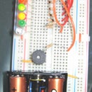
Step 4: Piezo


We will be coming back to this and will need to lift it to install jumpers to the Arduino but for now just put it in place with one pin on either side of the central divide so we don't short between the two pins.
The bread board pins are connected from left to right in two sections of 5 with a divide in the middle to separate the two sections, and the 2 outer pins are connected from top to bottom in two columns, these are on both sides but are not connected from one side of the board to the other, in other terms these can be used to provide two separate circuits independent of each other if required.
Additionally on some boards the top and bottom halves are not connected so you may have to make the jump using a wire from the top half to the bottom half if your circuit does not work.
Step 5: Button


The button has 4 pins, ensure these are all connected and don't bend then like with the Piezo have it sit across the central divider.
Next from the top wire the top right hand pin into the red side of the vertical pins, like the LEDs (see the 2nd image attached below)
Use the resistor BROWN BLACK ORANGE GOLD (10k) and wire it as shown in the 4th image attached below. (From the bottom right running vertically down the board, a small way 1 inch is enough).
Step 6: Resistors


Using the 220 ohm resistors wire from the LEDs across the divider to the same row on the opposite side, (See 2nd image for example) and repeat for all the LEDs.
Add the white LED beween the Piezo and button and add a resistor to that LED also.
The 3rd image below shows the final result. (note the GREEN wire is not necessary, unless your circuit doesn't work like mine did, it joins the top half of the boards power rails to the bottom half as some boards are split).
Step 7: Wiring


Now we are going to wire the Arduino to the breadboard, the wires all word in the order from top to bottom, and do not cross over so if the wrong lights come on at the wrong time patch the cables back in the right places...
Images below show how these should be wired.
Image 2 & 3: From the 5v line go to the resistor we placed coming out of the button.
Image 4 & 5: The green wire on the GND (ground) pin goes to the red rail which you connected the cathode of your LEDs to.
Image 6: The LEDs are wired in turn from pin 13 down to 8 starting at the top LED working your way down the bread board. This is why I said to have the board to the left as you can wire it as below...
13 o--------o ---/\/\/\/\/\--- ---O---|
12 o--------o ---/\/\/\/\/\--- ---O---|
11 o--------o ---/\/\/\/\/\--- ---O---|
10 o--------o ---/\/\/\/\/\--- ---O---|
09 o--------o ---/\/\/\/\/\--- ---O---|
Image 7: Wire the orange wires like before to the Piezo (pin 8), wait led (pin 7) and button (pin 6)
Note the position of pin 6 is critical other wise the traffic lights will constantly loop as if the button was held down.
Step 8: Programming Arduino


Programming the Arduino could not be easier, however we have to tell the Arduino IDE where to look for the Arduino and what type of Arduino to talk to.
To tell it what type to talk to go to TOOLS > BOARD > ARDUINO DIECIMILA.
To tell it where to look for the Arduino go to TOOLS > SERIAL PORT, and choose the most logical port, it will say usb serial or some thing similar, not bluetooth or any thing else, worst case scenario you get it wrong and have to set it to another port.
Now you to open the attached PDE file and upload it to the board, by pressing the button with an arrow pointing to some dots/...
-> |
This will take a few moments and if successful your Arduino will now be running the code, press the button furthest to the right (serial monitor) to control the board with a terminal like interface.
Attachments

Step 9: And They All Lived Happily Ever After... the End.
Through out the code I have written comments and you can read these to find out what each line does, and then try tinkering with it to see what happens, at worst case you can just restore it back to the original.
However if you need more help or guidance I have a few links and resources below...
Before I go I would like to thank Alex and the team at Tinker.it who taught me all I know on one of their Beginners workshops, they are truly brilliant at what they do, thank you!!! Also thanks to Sparkfun.com and Rapidonline.com who are an amazing resource of parts for arduino!
Links & Resources
Arduino.cc - This is the home of Arduino
Guide - This guide is recommended reading!
Rapid Online - UK Retailer for the parts I used today
Tinker.it - The UK Retailer of the Arduino
Digikey - US Retailer for the parts I used today
Sparkfun - The US Retailer of the Arduino
Electronics Information - Electronics information for beginners this site is amazing a great place to look for information about soldering, electronic components, resistor colour codes etc...
Thanks for reading, and have fun!
Participated in the
The Instructables Book Contest

![Tim's Mechanical Spider Leg [LU9685-20CU]](https://content.instructables.com/FFB/5R4I/LVKZ6G6R/FFB5R4ILVKZ6G6R.png?auto=webp&crop=1.2%3A1&frame=1&width=306)


