

Introduction: Arduino Mega RJ45 Plugs for Cable Management


Arduino Mega has tons of pins - that's a big reason for buying one, right? We want to use all those pins! Wiring can quickly become a spaghetti mess without cable management, though. We can consolidate wires by using Ethernet plugs. The data pins on the Arduino are mostly grouped in multiples of 8, and Ethernet cables have eight wires in them. This instructable explains how to fit four RJ45 Ethernet plugs onto the double header pins.
You will need:
- Soldering gun
- Solder (I use 0.8mm)
- Needle-nose pliers
- Wire cutters designed to cut flush with a surface, such as these: http://a.co/2LfGoG0
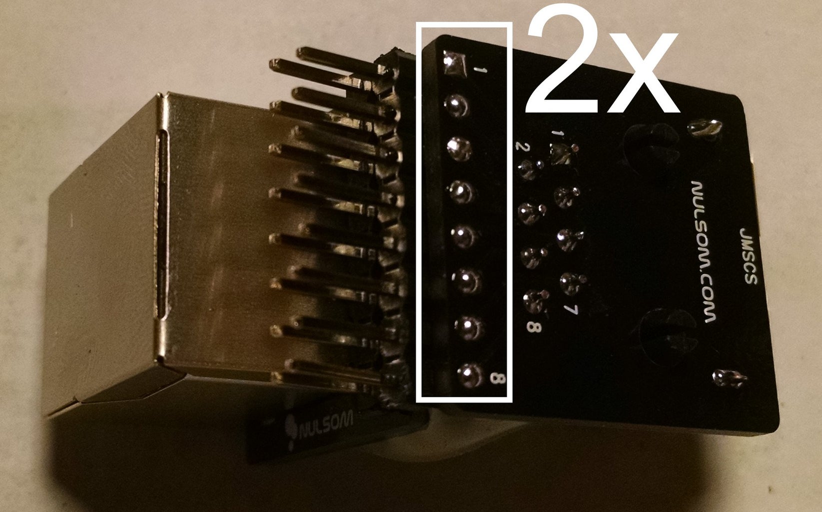
- Two packages of two ethernet RJ45 plugs: http://a.co/fEbVSmy
- A hot glue gun and two glue sticks
- A sharp knife, grinder, or dremmel tool
Step 1: Attach the Bottom Plug to the Arduino, Then Solder All the Pins (Gold Contacts)

You can buy the ethernet breakout boards at Amazon here: http://a.co/fEbVSmy
Step 2: Bend Header Pins (on Purpose) for the Second Row, and Cut Off Any Solder Bumps Sticking Up From Step 1


It is important that the pcb of the first RJ45 plug is smooth. Any metal pins that stick up might short circuit against the casing of the second RJ45 plug.
Step 3: Attach the Second Ethernet Plug and Pump Hot Glue Into the Crevice (arrow)

We use hot glue for two purposes:
- glue the two RJ45 plugs together
- insulate the back of the first plug from the casing of the second plug
Make sure to give the glue a minute to cool off.
Step 4: Remove the Plugs From the Arduino, Then Solder the Pins on the Second Plug... Twice.

The header pins for the second plug will probably not go 100% through the pcb after having bent them at an angle. Turn the pcb upside down like in the picture and solder all the pins. Then touch each of the header pins (in the white rectangle) with your soldering iron a second time, for a second or two, and add a tiny dab of additional solder. This will encourage the solder to wick down through the pcb and make good contact with the header pins. Obviously, don't add too much solder. It doesn't need much.
Step 5: Trim the Edges of the RJ45 Circuit Boards by 0.5mm

Now that everything is assembled, we just need to grind off a tiny bit of the RJ45 circuit boards on both the left and right sides. This will allow them to sit exactly next to each other. I recommend a bench grinder, but you could probably use a knife or dremel.


