

Introduction: Arduino Micro Electronic Bubble Level


A year or so back I built a camera pole level indicator that used L.E.Ds to indicate the angle of the tower as a visual aid. It worked good for what I intended but I've always thought it could be "jazzed up" a bit.
After picking up a little Nokia 5110 LCD display I decided to revisit my electronic level project.
This simple project is the result. I hope someone finds it useful!
Step 1: Parts Needed


for this project you'll need the following....
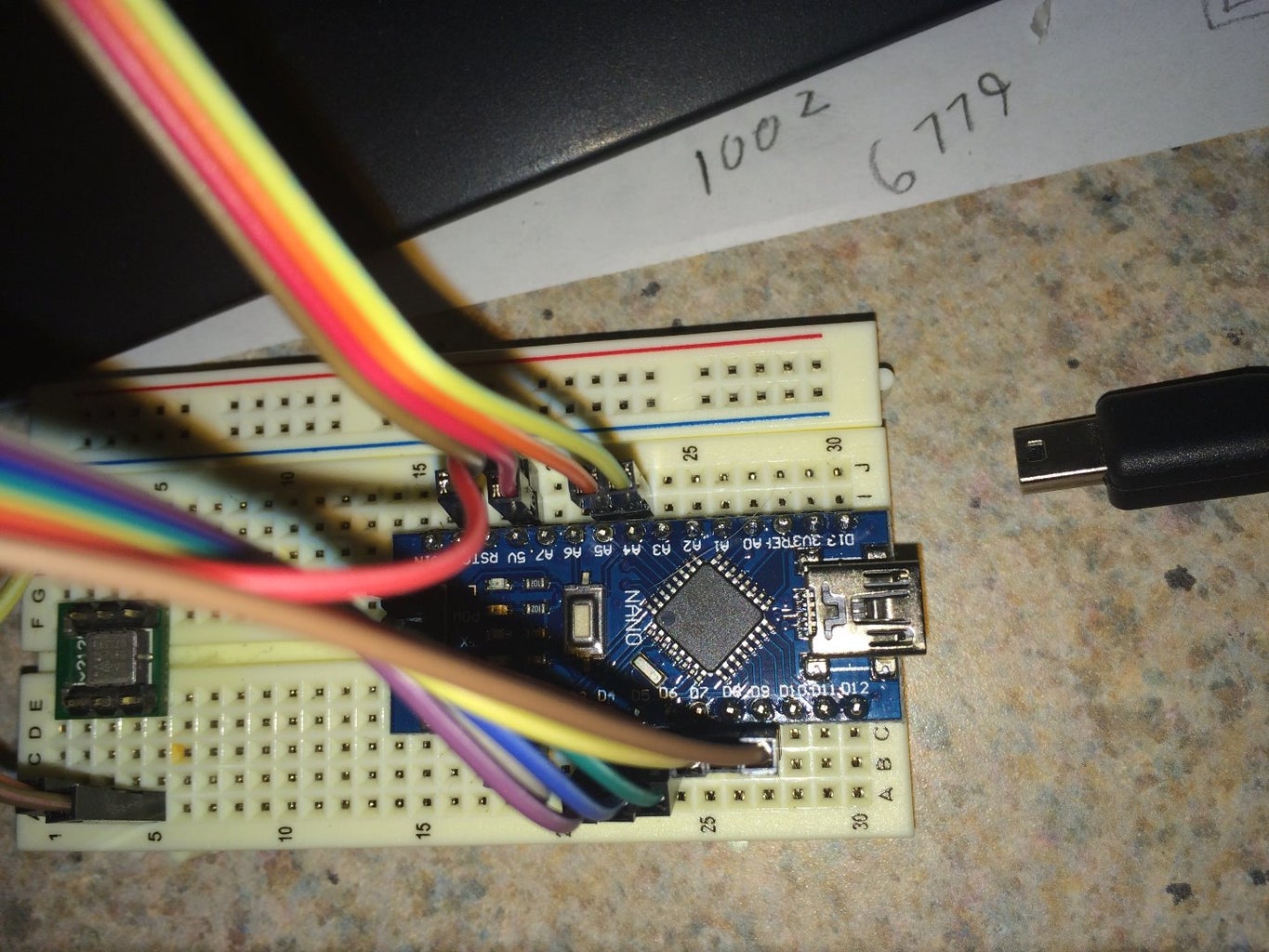
1. An Arduino. (I used a nano but any arduino should work)
2. A Tilt sensor. (I went back to the Memsic 2125. Mainly because I had some handy.)
3. A Nokia 5110 LCD display (Inexpensive and easy to find!)
4. Wires. (Many colorful WIRES!)
5. Breadboard or perfboard.
Step 2: Assembly Is Simple!

Assembly is super easy because it's all point to point. No separate components like resistors, capacitors and so on.
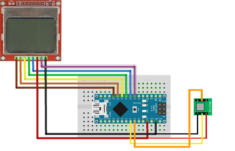
I included a simple pinout for the Memsic 2125 Tilt sensor.
The Nokia 5110 display units have the pin descriptions silk screened on them.
Here's a pin to pin listing for each part to the Arduino (nano) in my case.....
--------------------------------------
Arduino <------> Nokia LCD
GND ------------------- GND
5V -------------------- VCC
D4 --------------------- Light
D5 --------------------- CLK
D6 --------------------- DIN
D7 --------------------- DC
D8 --------------------- CE
D9 --------------------- RST
For the Memsic 2125
GND ------------------GND
5V ------------------VCC
A4 ------------------ XOut
A5 ------------------- YOut
Step 3: How Does It Work?

What makes it go?
the short answer is heat. The tilt sensor is actually a little chamber with 4 super tiny thermometers arrayed around it. as you tilt the sensor the heat rises and the thermometers measure the difference in temperature. it's that simple! The electronics in the chip convert the temperature differences into an X and Y measurement and send that data out the X and Y pins.
Step 4: The Code to Make It Go!
The code for this little project it pretty simple as well.
Since the sensor outputs it's signals as X and Y values. All we really need to do is read the values and convert them into something "real world" that we can display on our 5110 LCD.
The Code sets up the 5110 display. Draws a little bulls eye and then starts reading the x,y data from the memsic.
it then does a couple of mappings to convert the 3000 to 6000(ish) output into 2 values.
Stage one maps the memsic output to a scale for the display in both x and y (0-48) and (0-84) so we can display and animate the bubble around the display.
There's also a serial output that sends the raw data to the usb. you don't have to use it. but it's there if needed.
The second stage mapping then scales the display scales to -90 to 90 for the X ad Y text labels on the display for angles. (this is an approximate angle display) we're not worrying about accuracy without level. we just want a general idea!
Here's the code......
#include <SPI.h>

//arduino micro led visual level
#include <Adafruit_GFX.h>
#include <Adafruit_PCD8544.h>
Adafruit_PCD8544 display = Adafruit_PCD8544(5, 6, 7, 8, 9);
// pin 2 - Serial clock out (SCLK)     5
// pin 3 - Serial data out (DIN)       6
// pin 4 - Data/Command select (D/C)   7
// pin 12 - LCD chip select (CS)       8
// pin 11 - LCD reset (RST)            9


const int X = A4; //X pin on m2125
const int Y = A5; //Y pin on m2125
int i=0;
int dist,inv=0;
boolean stan=0;

void setup() {
   //set up serial
   Serial.begin(9600);

pinMode(X, INPUT);
pinMode(Y, INPUT);
display.begin();
display.setContrast(50);
display.clearDisplay();

 }

void loop() {


 //read in the pulse data
   int pulseX, pulseY;
   int angleX, angleY;
   int accelerationX, accelerationY;


  pulseX = pulseIn(X,HIGH);
  pulseY = pulseIn(Y,HIGH);

   //map the data for the nokia display
   accelerationX = map(pulseX, 3740, 6286, 48, 0);
   accelerationY = map(pulseY, 3740, 6370, 84, 0);
  // map data to crude angles
   angleX = map(accelerationX,48,0,-90,90);
   angleY = map(accelerationY,0,84,-90,90);
   display.drawRect(0,0,84,48,BLACK);
   display.drawLine( 42,  0,  42, 48, BLACK);
   display.drawLine( 0,  24,  84, 24, BLACK);
   display.drawCircle(42,24,10,BLACK);
   // display bubble
   display.fillCircle(accelerationY,(accelerationX),4,BLACK);
   display.setCursor(4,4);
   display.println("X: "+ String(angleX));
   display.setCursor(4,38);
   display.println("Y: "+ String(angleY));
   display.display();
   display.clearDisplay();


  //Send the data to the serial in case we'd like to see what's being reported and
  //possible pc use later
   Serial.print("X");
   Serial.print(pulseX);
   Serial.print("Y");
   Serial.print(pulseY);
   Serial.println("");


   // delay the data feed to we dont overrun the serial
   delay(90);
 }

Step 5: Lets See If It Works Like We Expect?
After all our hard work. Lets see if it does what we expect?
Looks like it works!
Once installed in a battery powered case it'll be ready for action!

Participated in the
Arduino All The Things! Contest


