

Introduction: Arduino Pocket Lightning Detector


We all enjoy working and playing outside. But I think anyone would agree that getting struck by lightning while having fun outdoors defiantly isn't... fun!
Ok enough with the Cute intro....
This project came about when, while I was searching around through the internet for sensors that I might like to try with an arduino as an interesting project. I also run a video camera for our local school district's football stadium and it's not uncommon to have Lightning delays. I thought this project might have some use in that regard as well. I have several Arduino nanos laying around and was itching to make something. In my searching I found the AS3935 Lightning detection sensor. Franklin as3935 (Here's a link to some data on it.) It's a low power lightning sensor that packs a lot of info into a small package.
Most Arduino lightning detection projects basically just tell you that something "lightning-like" occurred. This sensor actually watches for the particular Waveform of lightning at 500Khz and gives a distance approximation! Kinda of a cool little gadget to have in your pocket next time it thunders! I immediately wanted to try one out!!
This instructable is the result.
Step 1: Parts Needed


To do this build you'll need the following...
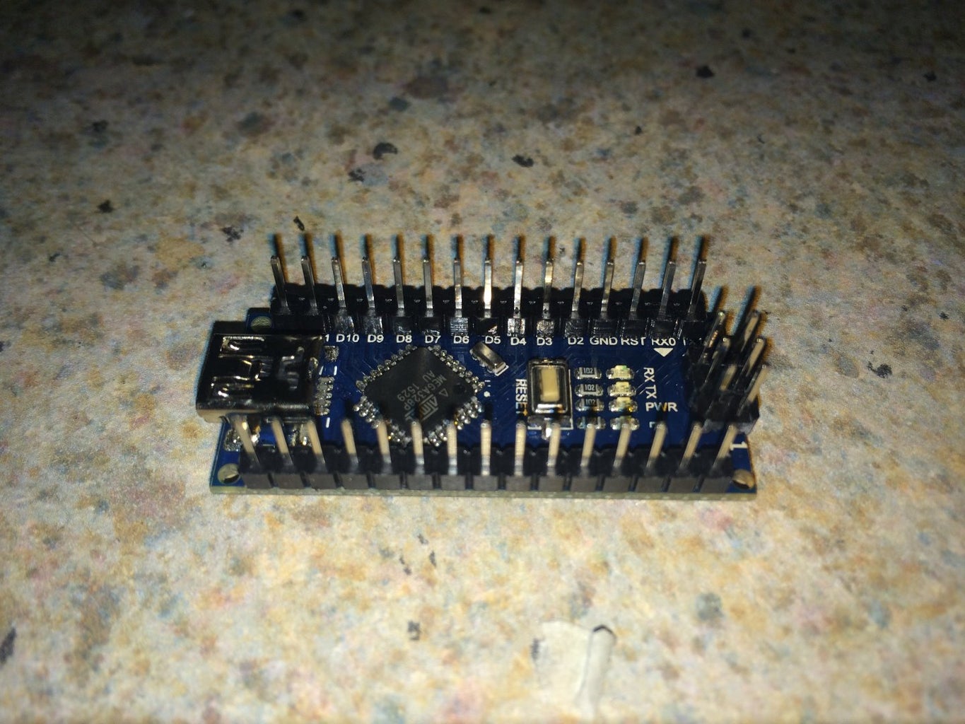
An arduino.
Most any Arduino will do. However if you're planning on your unit being portable. Obviously smaller is better.
-------------------------------------------------------------
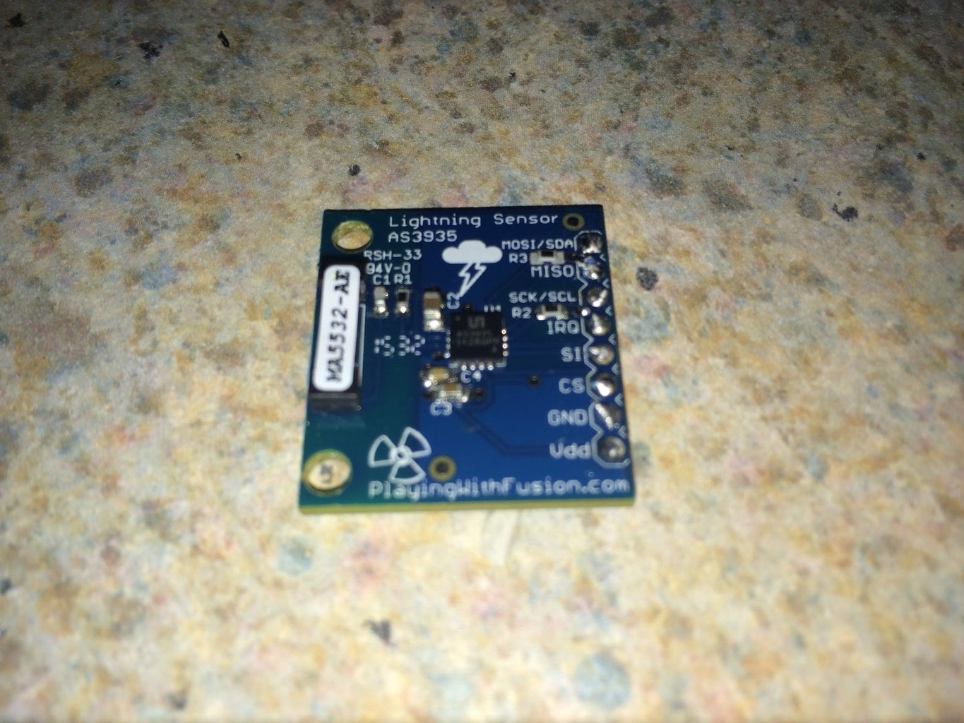
An AS3935 lightning sensor.
You can find these from any number of places. Here are a couple of links to get you started. Expect to pay about $20
--------------------------------------------------------------
Some kind of buttons or button panel.
>Ebay
--------------------------------------------------------------
A Nokia 5110 LCD display. Or some other display of your choosing.
Ebay nokia 5110 (a note of warning. I've ordered several of these and the quality is all over the place. Some are perfect. some have contrast problems. You can usually fix the contrast issues by pressing the metal frame down firm around the lcd)
--------------------------------------------------------------
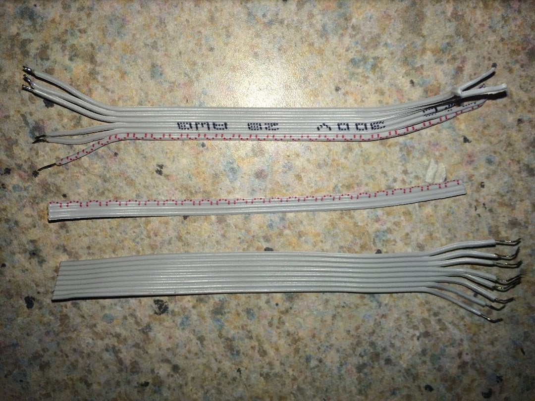
Some wire, solder and a soldering iron. Or if you prefer. Breadboard.
--------------------------------------------------------------
Early on I decided I wanted this to have some kind of a graphical display and a way to set some simple configuration. I also decided to just hardwire all the parts together so it would be stable when carried around in it's soon to be designed box. I also planned on it being battery powered and portable.
My first "throw together" prototype used a 16X2 LCD display but I soon realized the size limited the data I could display so I moved to a Nokia 5110 display Module. This would allow more data onscreen at one time and opened up the possibility of a little "monitoring activity" animation. It would also allow me to create a little stylized distance graphic. I needed some way to access the simple config menu and Decided to use a little Resistance button panel that allows the monitoring of several buttons with only one analog input. Each button on the panel gives a different reading value and that value can be the basis for accessing differing routines and the Arduino code. for interconnections of all the parts I used strips of ribbon cable to kind of help keep things clean and allow flexibility in placement of the parts inside whatever case I eventually came up with.
Step 2: Assembly
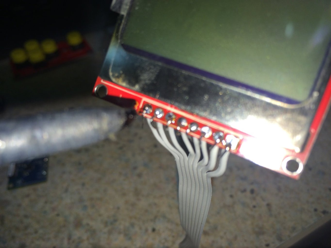
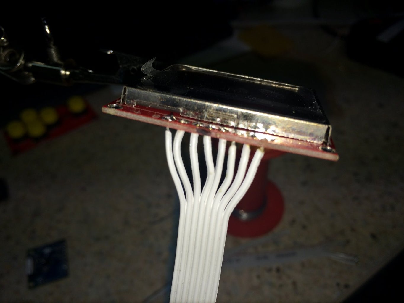


Assembly is pretty straight forward. All the connections are direct and there's no need for electrical component parts like resistors, capacitors or transistors. it's all point to point!
The Display will communicate with the Arduino via SPI. The lightning sensor communicates via I2C.
The Lightning sensor has the capability to utilize SPI or I2C. After some experimenting I found that for some reason having both connected via SPI was problematic. The lightning detection was not reliable and there were noise issues between the display and the lightning sensor. Changing the Sensor over to I2C cleared up the problems.
My circuit uses an Arduino Nano the I2C pins are SDA(A4) and SCL(A5)
(different arduinos use different pins. Check yours to find out which)
Here are the connections.....
Lightning Detector
Arduino Nano-------> AS3935 sensor
A4 --------------> MOS/SDA
(MISO not used)
A5 ---------------> SCK/SCL
D2 -------------- > IRQ
5V --------------- > SI (this pins selects what Communication type the chip uses. (+ = I2C, -=SPI)
( CS Not used)
Gnd ---------------- > Gnd
5v ---------------- > Vcc (power)
Nokia 5110 Display
(Pins are labeled in the back)
(Wider Silver edge is the top of the display)
Arduino Nano ----------> 5110 LCD
D4 -------------------------> RST
D5 -------------------------> CE
D8 ---------------------------> DC
D11 -------------------------> DIN
D13 -------------------------> CLK
5V --------------------------> VCC
D6 --------------------------> Light (making this pin low turns on the back light)
GND -----------------------> GND
Button Panel
Arduino Nano ---------------> buttons
GND -------------------> GND
5V -------------------> Vcc
A0 -------------------> OUT
Those are all the hardware connections. Reference the pseudo Schematic I included if you need help.
Step 3: Code and Icons


Now comes the part that makes it all work!
The code. Or in ArduinoSpeak (the sketch).
UPDATE: I found and corrected a small bug that Would cause the detector to freeze when it detected a unknown signal. I also added the ability for the detector to save the settings when powered off by storing the values in EEPROM. the updated code is in the zip file along with the original code. The updated code has the EEPROM appended to the file name within the zip file.
I also included the sketchup 3d printer files for the case.
The AS3935 Sensor basicly just sits and listens for lightnig via the small induction antenna on the breakout board. When it detects something it thinks is lightning or noise it triggers whats called an IRQ. This is a signal that is hard wired into the arduino that can cause it to stop and pay attention no matter what it's doing at the time.
When the Arduino sees the IRQ line change it stops whatever code it's running and jumps to a special bit of code that can read the data the sensor has stored about the particular event it's detected and then display or act upon what it finds.
In our case the Arduino sits and happily (or unhappily, who knows how it feels about it..) moving a little cloud bitmap across the display. Over and over.... it also momentarily looks to see if a button has ben pressed indicating the almighty user wants to change some settings.
If the Sensor pokes the arduino in the side with an IRQ. The arduino stops animating the little cloud and asks the sensor what it wants. The arduino then updates the display to show what it's learned.
The sketch also includes some rudimentary config settings like whether we want to know the lightning distance in Miles or Kilometers or if we're inside or outside.
I've included a zip file that contains all the files I've created in relation to this project. it also contains the libraries for the lightning detector board. It has everything you'll need to build this the same way I have.
The Nokia 5110 libraries are available in the Arduino IDE libraries manager. Just Search for adafruit GFX and LCD.
Here's the code.....
------------------------------------------------------------------
#include
#define eeprom_dist 4  //Define eeprom memory location to store mile or km calculation
#define eeprom_level 5 //Define eeprom memory location to store mile or km calculation

#include


/*
 * AS3935 communicates with i2c in this sketch
 * and the Nokia 5110 uses SPI
 */
#include
#include
#include

 Adafruit_PCD8544 display = Adafruit_PCD8544(8, 5, 4);

#include "I2C.h"
// include Playing With Fusion AXS3935 libraries
#include "PWFusion_AS3935_I2C.h"

// interrupt trigger global var
volatile int8_t AS3935_ISR_Trig = 0;

// define some values used by the panel and buttons
int adc_key_in  = 0;
int z=0;
int mi=0;
#define btnLEFT   3
#define btnDOWN   2
#define btnUP     1
#define btnRIGHT  0
#define btnSELECT 4
#define btnNONE   5

// defines for hardware config
#define SI_PIN               9
#define IRQ_PIN              2        // digital pins 2 and 3 are available for interrupt capability
#define AS3935_ADD           0x03     // x03 - standard PWF SEN-39001-R01 config
#define AS3935_CAPACITANCE   104       // <-- SET THIS VALUE TO THE NUMBER LISTED ON YOUR BOARD

// defines for general chip settings
#define AS3935_INDOORS    0
#define AS3935_OUTDOORS   1
#define AS3935_DIST_DIS   1
#define AS3935_DIST_EN    0

int l=0;
int n=0;
int lsDist=0;
int mapDist=0;
int m=0;
int dist=0;
int tt=0;
// prototypes
void AS3935_ISR();
//--- data that builds the onscreen icons
PWF_AS3935_I2C  lightning0((uint8_t)IRQ_PIN, (uint8_t)SI_PIN, (uint8_t)AS3935_ADD);
const unsigned char PROGMEM lightning_bmp[32] = {
0x01, 0xE0, 0x02, 0x20, 0x0C, 0x18, 0x12, 0x24, 0x21, 0x06, 0x10, 0x02, 0x1F, 0xFC, 0x01, 0xF0,
0x01, 0xC0, 0x03, 0x80, 0x07, 0xF8, 0x00, 0xF0, 0x00, 0xC0, 0x01, 0x80, 0x01, 0x00, 0x01, 0x00
};
const unsigned char PROGMEM cloud[32] = {
0x01, 0xE0, 0x02, 0x20, 0x0C, 0x18, 0x12, 0x24, 0x21, 0x06, 0x10, 0x02, 0x1F, 0xFC, 0x00, 0x00,
0x00, 0x00, 0x00, 0x00, 0x00, 0x00, 0x00, 0x00, 0x00, 0x00, 0x00, 0x00, 0x00, 0x00, 0x00, 0x00
};
const unsigned char PROGMEM lightning[32] = {
0x00, 0x00, 0x00, 0x00, 0x00, 0x00, 0x00, 0x00, 0x00, 0x00, 0x00, 0x00, 0x01, 0xF8, 0x01, 0xF0,
0x01, 0xC0, 0x03, 0x80, 0x07, 0xF8, 0x00, 0xF0, 0x00, 0xC0, 0x01, 0x80, 0x01, 0x00, 0x01, 0x00
};

int read_buttons()
{
 adc_key_in = analogRead(0);      // read the value from Button Panel. Values returned if a button gets pressed and which one it was....

 if (adc_key_in > 1000) return btnNONE;
 if (adc_key_in ==0 )   return btnLEFT;
 if (adc_key_in > 310 and  adc_key_in< 330 )  return btnDOWN;
 if (adc_key_in > 120  and  adc_key_in<145 )  return btnUP;
 if (adc_key_in > 480  and  adc_key_in<550)  return btnRIGHT;
 if (adc_key_in > 700 and  adc_key_in< 800)  return btnSELECT;
 return btnNONE;  // when all others fail, return this...
}

//-----------the config menu
void menu ()
{
  delay(400);
  while (read_buttons() != 4){
  display.clearDisplay();
  display.setCursor(0,0);
  display.setTextSize(1);
  display.println("Enter=Return");
  display.setCursor(0,8);
  display.println("Up = Mi");
  display.setCursor(0,18);
  display.println("down = KM");
  display.setCursor(0,28);
  display.println("Left=Indoors");
  display.setCursor(0,38);
  display.println("Right=Outdoors ");
  display.display();
  if (read_buttons() == 1){
 mi=0;
 EEPROM.write(eeprom_dist,0); //Write setting for (1)Mile/(0)Kilometer calculation to EEPROM for recall after power off
  display.clearDisplay();
  display.setCursor(0,0);
  display.setTextSize(1);
  display.println("Set to KM");
  display.display();
  delay(1000);
  menu();
  }
  if (read_buttons() == 2){
 mi=1;
 EEPROM.write(eeprom_dist,1); //Write setting for Mile/Kilometer calculation to EEPROM for recall after power off
 display.clearDisplay();
  display.setCursor(0,0);
  display.setTextSize(1);
  display.println("Set to Miles");
  display.display();
  delay(1000);
  menu();
  }
  if (read_buttons() == 0){
 lightning0.AS3935_SetIndoors();
 dist=0;
 EEPROM.write(eeprom_level,0); //Write setting for (0)Indoor/(1)Outdoor setting on AS3935 to EEPROM for recall after power off
 display.clearDisplay();
  display.setCursor(0,0);
  display.setTextSize(1);
  display.println("Indoor");
  display.setCursor(0,20);
  display.println("Operation");
  display.display();
  delay(1000);
  menu();
  }
  if (read_buttons() == 3){
 lightning0.AS3935_SetOutdoors();
 dist=1;
 EEPROM.write(eeprom_level,1); //Write setting for (0)Indoor/(1)Outdoor setting on AS3935 to EEPROM for recall after power off
 display.clearDisplay();
  display.setCursor(0,0);
  display.setTextSize(1);
  display.println("Outdoor");
  display.setCursor(0,20);
  display.println("Operation");
  display.display();
  delay(1000);
  menu();
  }
  }
  return;
 }


void setup()
{
  mi = EEPROM.read(eeprom_dist); //Read Stored Settings from EEPROM
  dist = EEPROM.read(eeprom_level);  //Read Stored Settings from EEPROM
  pinMode(6,OUTPUT);
  Serial.begin(115200);
  display.begin();
  // init done

  // you can change the contrast around to adapt the display
  // for the best viewing!
  display.setContrast(25);

  display.display(); // show splashscreen
    display.clearDisplay();
     display.setCursor(0,0);
      display.setTextSize(1);
    display.println("Raht Lightning   Detector");
    display.setTextSize(1);
    display.drawBitmap(35, 22,  lightning_bmp, 16, 16, 1);
  display.setTextColor(BLACK);
  display.display();
  flash();
  display.display();
  delay(3000);

  // setup for the the I2C library: (enable pullups, set speed to 400kHz)
  I2c.begin();
  I2c.pullup(true);
  I2c.setSpeed(1);
  delay(2);

  lightning0.AS3935_DefInit();   // set registers to default
  // now update sensor cal for your application and power up chip
  lightning0.AS3935_ManualCal(AS3935_CAPACITANCE, AS3935_OUTDOORS, AS3935_DIST_EN);
                                 // AS3935_ManualCal Parameters:
                                 //   --> capacitance, in pF (marked on package)
                                 //   --> indoors/outdoors (AS3935_INDOORS:0 / AS3935_OUTDOORS:1)
                                 //   --> disturbers (AS3935_DIST_EN:1 / AS3935_DIST_DIS:2)
                                 // function also powers up the chip

  // enable interrupt (hook IRQ pin to Arduino Uno/Mega interrupt input: 0 -> pin 2, 1 -> pin 3 )
  attachInterrupt(0, AS3935_ISR, RISING);
  lightning0.AS3935_PrintAllRegs();
  AS3935_ISR_Trig = 0;           // clear trigger

}

//------- this just gets played over and over..... and over...... and o......
void loop()
{
  display.clearDisplay();
  analogWrite(6,60); //---turn on the backlight
  //----- build the screen
   display.setCursor(0,0);
   display.println("LastStrike");
   display.setCursor(0,8);
   display.println("Dist: "+ String(lsDist));
   display.setCursor(50,8);
   //--- if we pick miles, do this
   if (mi==1){ display.println(" Mi");}
   //otherwise assume we want to do this....
   else { display.println(" Km");}
   display.setCursor(0,17);
   display.println("0");
   display.setCursor(72,17);
   //if miles--- 40 km = aaprox 25 miles
   if(mi==1){
   display.println("25");
   }
   else{
   //--- otherwise just scale it for 40 km
    display.println("40");
   }
   display.setCursor(0,39);
   display.println("Strikes: ");
   display.setCursor(48,39);
   display.println(String(l));
   display.setCursor(64,39);
   //-- place an indication that we're set to inside in the lower right corner of the display
   if (dist==1){display.println("Out");}
   else{
    //-- or Show were set for outdoors
    display.println("In");}
    //--draw the distance scale
   display.drawLine( 0,  37,  84, 37, BLACK);

   display.drawLine( 0,  25,  0, 37, BLACK);
   display.drawLine( 21,  35,  21, 37, BLACK);
   display.drawLine( 42,  35,  42, 37, BLACK);
   display.drawLine( 63,  35,  63, 37, BLACK);
   display.drawLine( 83,  25,  83, 37, BLACK);

   //display.fillCircle(mapDist,35,2,BLACK);
   if (l==0)
   //-- we begin with no strikes detected
   display.setCursor(9,24);
   display.println("No Strikes");
   if (l>0)
   //-if theres a strike. place a little zap at the distance it is...
   display.drawBitmap(mapDist, 22,  lightning, 16, 16, 1);
   if (mapDist>20){
    display.setCursor(9,24);
   display.println("Far Ligntning");
   }
   display.display();

  if(0 == AS3935_ISR_Trig){
  //   Serial.println(read_buttons());
  animateCloud();
  //Serial.println(read_buttons());
  if (read_buttons() !=5){
      menu();
  };
  // reset interrupt flag
  AS3935_ISR_Trig = 0;

  // now get interrupt source
  uint8_t int_src = lightning0.AS3935_GetInterruptSrc();
  if(0 == int_src)
  {
 display.setCursor(72,0);
  display.println("?");
 display.display();
  //delay(1000);
 display.setCursor(72,0);
  display.println(" ");
  }
  else if(1 == int_src)
  {
    flash();
    uint8_t lightning_dist_km = lightning0.AS3935_GetLightningDistKm();
    display.clearDisplay();
    l++;
    display.println("  Lightning!!");
    if (mi==1){
    lsDist=(lightning_dist_km  * 0.62137);
    }
    else{
     lsDist=(lightning_dist_km);
    }
    display.println((lsDist));
    mapDist = map(lsDist, 0, 25, 0, 83);
    display.println(" Miles");
    display.display();
    flash();
  }
  else if(2 == int_src)
  {
    //display.clearDisplay();
  display.setCursor(72,0);
  display.println("N");
  //  n++;
   display.display();
  delay(1000);
  display.setCursor(72,0);
  display.println(" ");
  }
  else if(3 == int_src)
  {
    display.clearDisplay();
 display.println("Noise level too high");
 display.display();
 delay(500);
  }
//  lightning0.AS3935_PrintAllRegs(); // for debug...
}
}

// this is irq handler for AS3935 interrupts, has to return void and take no arguments
// always make code in interrupt handlers fast and short
void AS3935_ISR()
{
  AS3935_ISR_Trig = 1;
}
//---flash the display routine
void flash(){
  for (int y=1;y<5;y++){
    digitalWrite(6,LOW);
    display.invertDisplay(true);
    delay(100);
    digitalWrite(6,HIGH);
    display.invertDisplay(false);
    delay(100);
  }
}
//--make that cloud go baby!!
void animateCloud(){
    display.drawBitmap(m,15,  cloud, 16, 16, 1);
  display.display();
  if(m>=80){m=0;}
    m++;
  delay(200);
}
Attachments

Step 4: Designing and Printing a Case


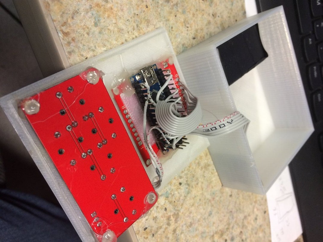


Next came the fun of designing a case to hold my little creation.
Not the most beautiful thing in the world. But it's functional.
In order to design a case I needed to know the dimensions of the parts involved. Namely the LCD display and the button panel.
3d printers are so cool! Now if I only had a laser cutter! ;)
The measurements for the Nokia 5110 were easily obtained. The button panel however... that was a different story! I ended up measuring... printing... re-measuring... printing... until I was pretty happy with the fit.
I've included the results in the form if a diagram in the hopes it saves someone else some time!
The case I designed wont win any design awards. It's simple, functional and, slightly translucent! I plan on adding some led's later so the case will glow or flash when a lightning strike is detected. Why not? I have plenty of pins left on the Arduino! I might also add an SDcard slot to log data! Or you could do that! The possibilities are endless!
Back to the case... basicly it's a box. just a box with holes for the buttons and the display. It'll hold the guts and a 9V or AA battery pack.
For starters I'll just hot glue all the parts in their places to see if it all fits and works reliably.
Step 5: Testing and Use


Now for the Real part! Seeing it work in the field... now if We'd only get some thunderstorms!
I've included some videos of the detector starting up and the setting of the limited configuration parameters.
If by the time I publish this Instructable I haven't had any storms to test it with. I'll upload some videos later.!
Update: We had a small thunderstorm with some very sporadic lightning. I was able to take a couple of photos of some lightning detections.
BTW.. please excuse the music on the one demo video. Someone was talking to me over the desk when
I was shooting it and I thought I'd spare you the conversation! =)

Participated in the
Robotics Contest

Participated in the
Tech Contest

Participated in the
Epilog Contest VII


