

Introduction: Arduino Mood Gauge With Clock


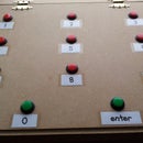


Here's my mood gauge. It started out as a 'I know what we need...' discussion in the office, but since making it I think it could also function as a child behaviour monitor for parents or a RAG/traffic light gauge for teachers - albeit an elaborate one. Quite simply, as illustrated by the animated gif above, you push a button to display the corresponding mood - so everyone who's looking will know what mood you're in (and will know to tread carefully if it's showing red). Additionally I've added a clock function as there were enough pins left over on the Arduino to do so. In-keeping with the 'mood' theme of this project I decided to the clock should show a 'mood' depending on what day of the week it is - obviously Monday is bad and Weekends are good!
Items I used:
- 3mm thick sheet of MDF (around A3 size)
- 16x32 RGB LED matrix I used this one
- Arduino Uno
- Arduino Uno Case
- RTC - I used a cheap DS1307 from ebay
- 2x short stand-offs (for fixing RTC to board)
- Arduino header pins (at least 4)
- Red, amber and green momentary push buttons
- A toggle switch
- Various Jumper wires with Dupont male and female connectors
- A power bank with 2 USB ports (for portability)
- USB Power Only Cable with Switch (like this one)
- 2x Molex - MX-33012-3001 female connectors for AWG 14-16 (like this: for powering the LED matrix)
- A short USB type A/B cable
- Heatshrink, for neatening spliced cables
- Primer and spray paint
- 4x thin metal strips (for the magnetic feet of the LED matrix to stick to)
- Masking tape/Masking film
Tools I used:
- Scalpel/Stanley knife - 3mm MDF can be easily cut with this
- Metal ruler - to guide the scalpel knife
- Glue gun
- Hand drill
- Soldering Iron and solder
- Wood glue/superglue
- Hand drill + drill bit wide enough for the push buttons
- Crimper + wire cutter
- Spray mask
Step 1: Powering the LED Matrix

My first step was to power the LED Matrix. There is a method described on the Adafruit website here however that looked bulky and messy to me. As my LED Matrix was the Molex-style header one, I decided to get a USB Power Only Cable with Switch, as this is rated for 2amp (the max draw from the LED Matrix) then I cut it at the switch, crimping the Molex - MX-33012-3001 female connectors to the red and black wires in its place. These then fix to the outer header pins on the back of the LED Matrix (VCC and GND - as described on the Adafruit website).
Also, as there are limited ground pins available on the UNO and the 16x32 LED matrix uses 4, I decided to splice together a ground wire for these 4 that would run to a single ground pin on the Arduino. For reference here's a good spicing guide. I used heatshrink to cover any exposed wire.
Step 2: Wiring It Up


The next step was to wire it all together, and get something working. The process for wiring the LED Matrix is pretty well documented on the Adafruit website: there are several options but I chose the jumper wire method here however I wired it directly and omitted the ribbon supplied with the LED Matrix. As documented on the Adafruit site, the wiring procedure varies depending on the size of the matrix and whether you are using a Mega or Uno - obviously I'm using a 16x32 Matrix and an Arduino Uno, so I followed the instructions listed for this hardware in particular, but for clarity I include a Fritzing diagram above.
I also spliced the ground for the toggle and push buttons and wired their positive (+) to a separate pin on the Arduino. While the RTC I bought is a cheaper imitation, there's further documentation for assembly, wiring and the code libraries on the Adafruit website here. The diagram above also shows how I connected this to the Arduino.
Step 3: The Code

You will need to include several Arduino Libraries to get this working: one for the RGB Matrix Panel hardware here; one for the GFX graphics here; and one for the RTC here. There's also a good tutorial for adding libraries should you need it here.
After including the libraries, I used the example codes and some other tutorials online to cobble together this Sketch: the sketch I used has been attached to the bottom of this step.
There may be a better way to achieve the same outcome, however much of this was trial and error. I learnt that the brightness of the LEDs is dependent on the colours you assign: the LEDs are quite bright so the colour hues that I chose are as dim as I could get them. Additionally I decided to add a 'mood' to the clock display depending on what day of the week it is, as in the image above: essentially dayOfTheWeek() == 0 is Sunday and dayOfTheWeek() ==6 is Saturday.
Attachments

Step 4: Preparing the Mounting Board


I took my piece of 3mm thick MDF and laid out roughly where each item would sit then cut it down accordingly, keeping the off-cut handy. I simply used a ruler and scalpel knife to make the cuts - as the MDF is so thin it just takes a few scores with firm pressure to cut right the way through.
Bearing in mind the LED Matrix, with its legs, sits 2.5cm away from the rest of the board, I decided the push buttons should be easily accessible beneath it and so opted for a raised angled surface on which they could sit, as shown in the pictures above. To achieve this I cut along the 3 solid black lines as illustrated by (1) in the image above, then from behind along the dashed line, but only part way through as this will then fold upwards (2), where, using the off-cut MDF, the pieces necessary to complete the triangular pyramid shape (3) are fashioned and glued in to place using wood glue. For extra strength I used a glue gun from behind to make a bead of glue along the inside edges and vertices.
Also, using the off-cut MDF, I made the housing for the power bank by cutting strips to the size and dimensions required to accommodate my particular model. As the whole board will sit upright it was necessary to include a front (of sorts) to the power bank housing to stop the power bank itself from tipping out. This was all cut and glued directly in to place and simply left to dry.
Also, though not shown in the images, I positioned the LED Matrix in place in order to get the push buttons correctly aligned with the graphics on display. I then drilled out the holes using a drill bit wide enough to allow the threaded part of the push button through but not the lip.
Step 5: Masking and Painting

The next step was to make it much more presentable. I started by lightly sanding the board and any edges then applied a few coats of white primer. I then glued on 4 metal strips (in the top-right picture above) in line with where the legs of the LED Matrix will sit: as it's magnetic, I made these metal strips bigger than the magnets on the legs of the LED Matrix to allow for me to easily tweak the positioning of it later, if necessary. These were just glued in place with superglue.
Before spraying the final coat I decided to mask certain areas so the white would show through - making the final aesthetic less plain-looking. I used masking tape to create a border and to mask the Power Bank housing, and masking film to make a feature of the toggle switch area - so I could add labels later.
Once all masked I took it outside (good ventilation is essential) and applied several thin coats to build up the layers. The colour, incidentally, I just had left over from another instructable project I did here. Having left it to dry for an hour, I peeled away all the masking.
Step 6: Final Assembly

Next was the fun part - watching it all come together. I soldered the push buttons and the toggle switch, and cut all wires to length so there was little slack. I crimped the necessary Dupont pins using a crimping tool and covered with pin-connector housing. Then I fixed the Uno case; aligning the holes first, drilling small pilot holes into the board then screwing the screws supplied straight into it. The rest of the case I added around the Arduino once it was fixed through the bottom piece directly onto the board. Finally I mounted the RTC on 2 stand-offs.
Step 7: Admire


Runner Up in the
Microcontroller Contest 2017


