

Introduction: Arduino Music Rhythm LED Lighting Box


In this project I will show you how to make your own Arduino (based) music rhythm LED lighting box,
The circuit uses the ATtiny45 micro-controller and you will be able to program it with Codebender - online Arduino ide - by using the Arduino UNO board as an ISP programmer.
The hole procedure is very easy and the cost is below 10$.
Please note that this is a simply way to make an led lighting effect by reading sound values from an analog input pin. So, it's not the correct way to analyze sound/audio signals but it will flash the LEDs in music rhythm.
Watch the presentation video below and please subscribe to our YouTube channel to help us grow up!
Official project page: http://www.ardumotive.com/music-rhythm-led-lighting-en.html
You can also use the Arduino uno board (or any other board) but you have to find first the analog values by using the serial monitor and make the necessary changes in the code that you will find below.
So, let's get started!
Step 1: What You Will Need
For the circuit you will need:
- ATtiny45
- 8 pin DIP IC
- Socket
- 3x LEDs
- 3x 68 ohm resistors
For the Arduino as an ISP programmer:
- Arduino uno board
- Breadboard
- 10uF capacitor
- 6 breadboard cables
For box:
- Plexiglass pieces, thickness 4 or 5mm, white color with 50% transparency:
Up side: 15x5 cm
Front side: 15x6 cm
Bottom side: 15x7 cm - Balsa hood (or MDF) pieces:
Back side: 15x5 cm
Left and right sides: ~5.8x5.8 cm (2 pieces)
Inside walls: 5x5 cm (2 pieces)
Tip: You can also use a cardboard instead wood.
Step 2: Set the Arduino UNO Board As an ISP Programmer
Here's the "Arduino ISP" code, embedded using Codebender!
Codebender is an online Arduino IDE - It's the easiest way to program your Arduino board directly from your browser! Just click on the "Run on Arduino" button and that's it! Try it! It's really amazing!
Step 3: Connecting the Arduino Uno With the ATtiny45


The connections are pretty easy, see the above image with the breadboard circuit schematic.
Tip: The dot in the corner of the ATtiny shows the first pin.
- Pin 1 to Arduino pin 10
- Pin 2 -
- Pin 3 -
- Pin 4 to Arduino GND pin
- Pin 5 to Arduino pin 11
- Pin 6 to Arduino pin 12
- Pin 7 to Arduino pin 13
- Pin 8 to Arduino 5V pin
Connect a 10uF electrolytic capacitor between Arduino uno reset pin and ground.
Note: The stripe on one side of the capacitor shows the negative pin and should connected with ground.
We will use the capacitor because it prevents the Arduino UNO from resetting, so we are sure that the Codebender (or Arduino IDE) talks to the ArduinoISP, and not with the bootloader, during the upload of sketches.
You can now connect again the Arduino uno to your computer.
Step 4: The Code

We will use Codebender - online Arduino IDE - to program the ATtiny45 micro controller.
Click here to connect with your Codebender account.
New to Codebender?
Codebender is an online Arduino IDE, and free of use! Why Codebender? You can write and program your Arduino boards from your browser and the best part is that you can store all of your sketches online! So there accessible from everywhere! Also you can share them with your friends and social networks. With 517 builtin libraries, Codebender offers the most comprehensive list of Arduino libraries in the world, and you can simply include them in your projects to use them.
Click here to make your new Codebender account for free!
Make a new sketch
and copy-paste the code below.
For the next steps see the above image:
- Select port (mine is COM3)
- Select from boards menu the ATtiny45 with 1MHz internal clock
- Click on advanced options button (gear icon on the right)
- Select "Arduino as ISP"
- Press the "Run on Arduino" button
That's it, you've programmed the ATtiny45 with this sketch!
Step 5: The Circuit

Step 6: Audio Jack: Input and Output


Take a male to female audio (with 3.5mm jack) cable and cut it in the half.
Connect the "inside" cables again but this time connect also an extra cable to ground and an extra cable to left (or right) channel.
The 'extra' cable from the left channel will be connected with the analog pin 3 of ATtiny45.
See the images above.
Step 7: Power: Use an USB Cable

The best option is to use an USB cable to power on our LED box.
You can also use batteries (max 5V).
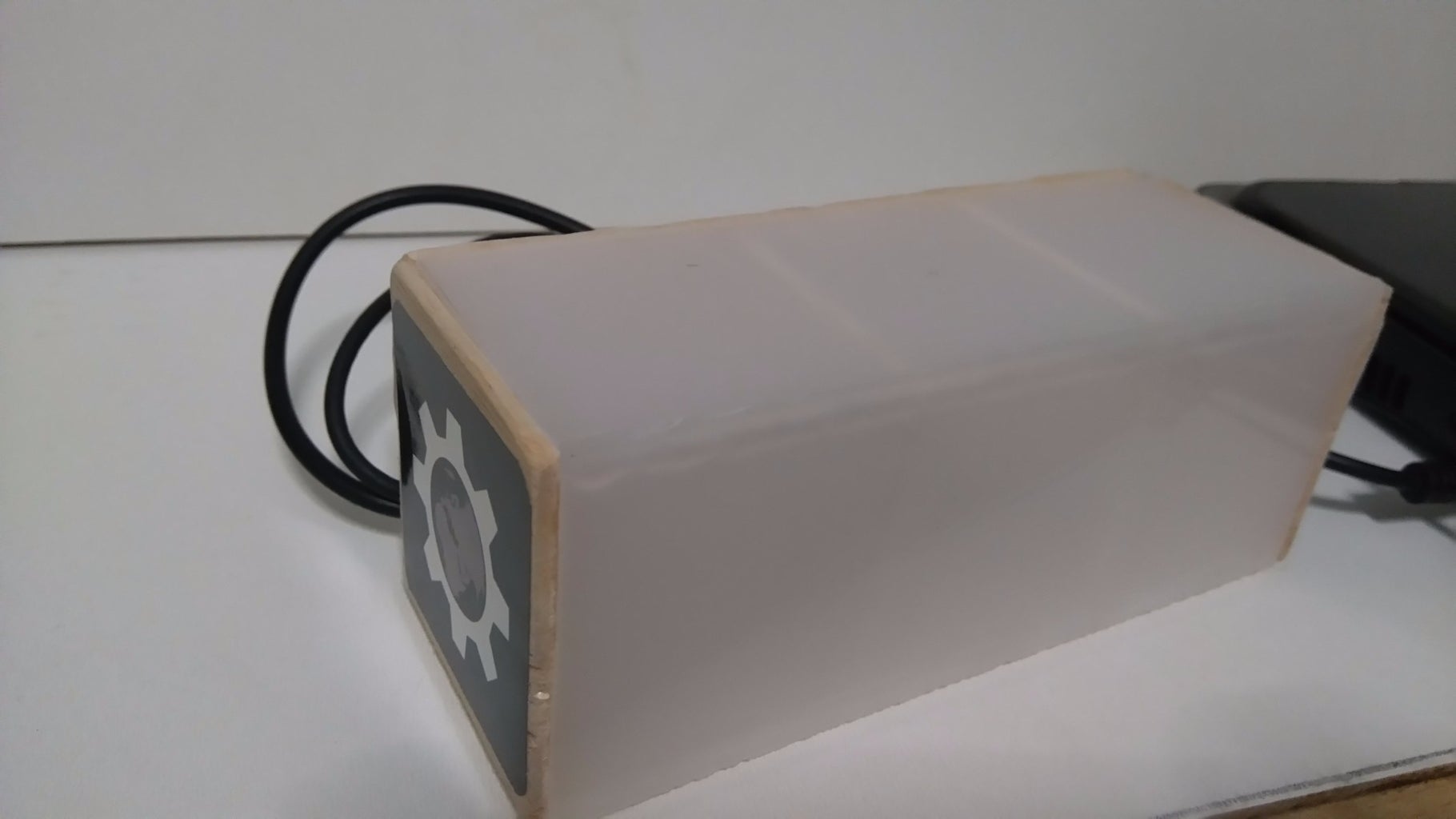
Step 8: The Box and the Final Circuit


The first image above shows with red lines where you need to use wood pieces.
- Glue plexiglass pieces (up side, front side and bottom side)
- Glue the wood pieces (left, right and inside walls)
- Put the 3 LEDs to back side wood piece (turn them to face the bottom side)
- Solder the circuit on pcb
The above images will help you understand more.
Step 9: Well Done!

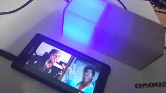
Now you have your own music LED lighting box on your desk!
I would like to see photos of your construction!
I hope you liked this, let me know in the comments below.

Participated in the
Arduino All The Things! Contest

Participated in the
Make It Glow! Contest


