

Introduction: Arduino Obstacle Avoidance Robot


Note: The board can easily be modify to be mounted on a car chassis to make an obstacle avoidance car all you have to do is mount the board horizontal and bend the IR transmitters and receivers forward.
A few months ago I found a box of some electronics project I built a long time ago when I was younger. I found a kit that was made by OWI the Spider Kit, it was missing the pcb board but everything else is there including the manual. My 6 year old daughter was fascinated by it and wanted me to make it work. The original PCB uses transistors to build and H-Bridge and drive two dc motors it uses an IR Transmitter and receiver to detect obstacles..
I am planning on using an Arduino nano and IR sensors. I am designing a different head that It can be printed in a 3d printer to accommodate the different sensors. I will writing the firmware that you will be able to modify and play with using simple functions. I am designing everything so that you will be able two build and modify very easily. This is going to be a great project for who wants to get into robotics and to learn how to use arduino. I already have design the PCB and Head for the IR version, I was thinking of creating an ultrasonic version but maybe at a later time.
Step 1: How It Works

The Original circuit uses a red led to emit pulses of light and a phototransistor as a receiver, the pulses are fed into an op-amp to amplify the signal. The motor are always "on" when the power is turned on, when an obstacle is detected a motor reverses the rotation direction to turn and avoid the obstacle, there is also a timer that uses a capacitor so that the change in direction doesn't end so rapidly that the robot is not able to avoid the obstacle.
Since it wouldn't be fun to build the original circuit and PCB, we are upgrading and we are going to be using an arduino to control the body of the spider. In this case we do not have a lot of room in the head so we have to use a nano version . The whole circuit works the same, in theory we are just using a micro controller to eliminate some circuitry and several components. We have the micro controller, IR transmitter and receiver, an amplifier, and our h-bridge IC to drive the motors.
The biggest change and the actual purpose of this project is to give the robot the ability to detect the location of the obstacle and avoid accordantly. instead of a single transmitter and receiver like on the original we have one on each side, if we detect an obstacle on our right we turn left, if its on the left we turn right if its too big we go back and turn the go forward. The beauty of using the arduino is that we are able to also control the speed of the motors an in turn the actual walking speed of the robot by just modifying a line of code.

Step 2: What You Will Need

List Of Materials
1x Custom PCB
1x Arduino Nano
1x L293D Motor Driver
1x 7805 Voltage Regulator
2x LM358N Op-Amp
2x 1k Variable Resistors
2x 5mm IR Transmitter
2x 3mm IR Receivers
2x 3mm LEDs
4x 1k Resistors
2x 10k Resistors
1x 9V Battery
Step 3: PCB Design


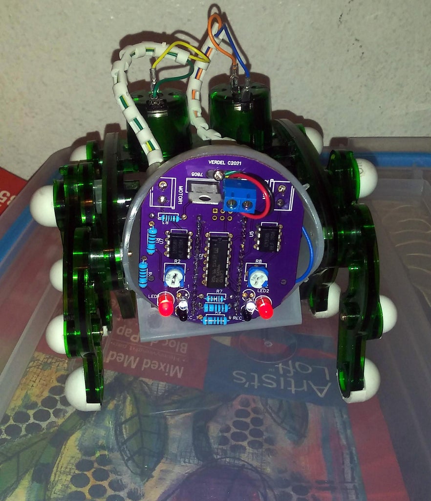
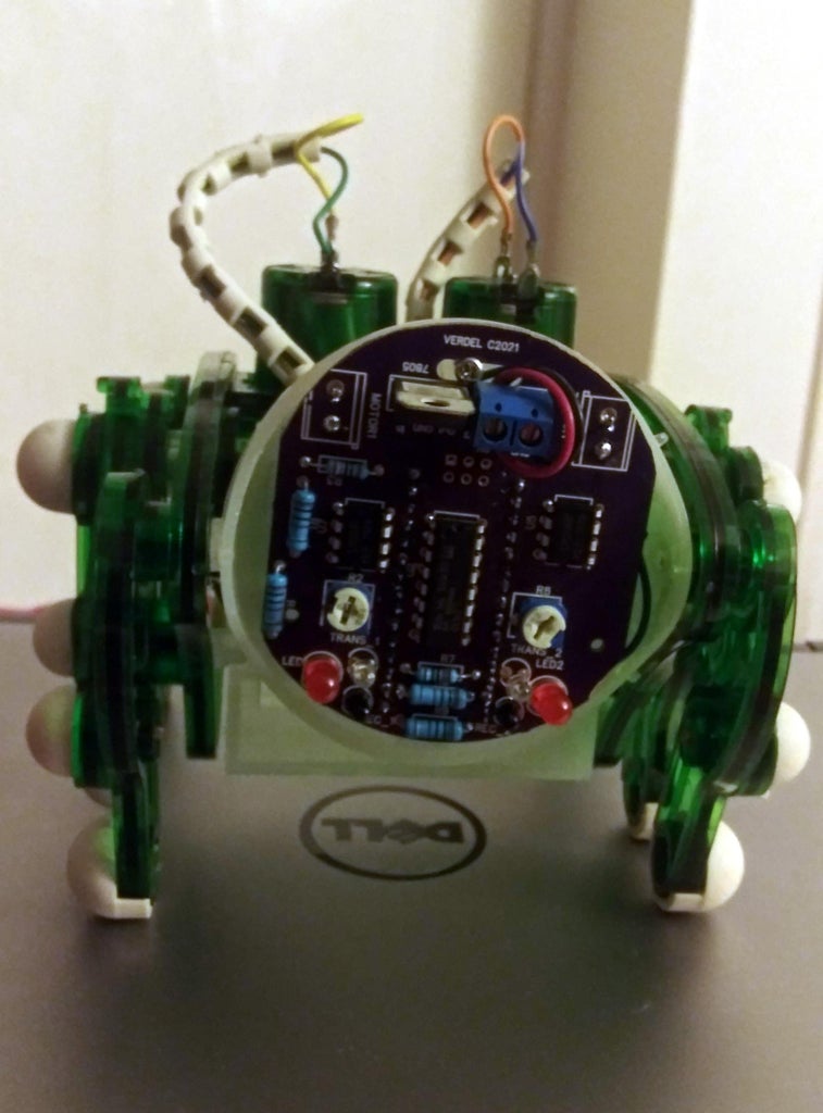
The PCB is a 2 layer for obvious reasons there is just not enough room for all the components on one side, I decide to place the arduino nano in the bottom so that all the other components would fit on the top layer and it would be easier to assemble and wire.
The original circuit uses a 9V battery and 2 AA batteries, we can run our robot using only the 9V battery by dropping the voltage to 5V. Most of the components run on 5V, the motor drivers inside the L293D can handle up to 36V, so we will feed the 9v to run the DC motors.
the Op-amp will be used as a comparator, we need to add a variable resistor so we can adjust our reference voltage or our detecting distance.


Step 4: Head CAD


Note: if printing the front cover you need to mount the IR LED's on the cover then run wires to the PCB.
The original robot had only one IR transmitter and a single receiver. The new controller has 2 transmitters and dual receivers also I have added two additional LEDS for fun and because who wants a spider with 4 eyes? spiders should have 8 or 10 eyes. That created a problem because we are not able to mount them in the original head. So we need to re design the head because there are other issues with fitting the PCB so we need to redesign both pieces of the head.
Did a quick sketch on a paper, then the modelling on blender. I have included all the files you will need to print the two pieces, you will need to play with the settings depending on your 3d printer. I could not make it work on ultimaker cura had issues with the scale. I ended up using creality slicer. My printer stop working half ways so I don't have a a complete head.
Attachments
Step 5: Firmware

The code is very simple the L293D gives us the ability to control the speed and direction of the motors. We use PWM (Pulse Width Modulation) to control the speed of the motor . To control the direction we use the H-Bridge circuits inside the L293D.
There are several functions that we use to control the robot.
Forward () = Forward
Back () = Reverse
Right () = Turn Right
Left () = Turn Left
Speed() = Motor Speed 0-255
if sensor right and sensor left are LOW then we kwon that the is no obstacle and we can move forward.
If one of the sensors turns HIGH then we have an object present so we turn in the opposite direction to avoid it.
if both sensors turn HIGH we would go in reverse, turn then we would keep going forward.
Attachments
Step 6: Improving and Future Experiment
*I have been thinking that I need to pulse the IR signal to make it more efficient .
*adding or replacing the IR Sensors with Ultrasonic Sensor I think would be better for navigating.
*I was going to make the firmware more complex in how decisions are made instead of just being black or white but this was a project to teach my 6 year old daughter how to make arduino detect objects and control the motors to avoid them. I think that overall it was a successful and fun project for both of us.
If any of you have questions or suggestions please feel free. Thank you all and until the next instructable.

Participated in the
PCB Challenge


