

Introduction: Arduino Passive Preamp With Remote, Attenuator and Channel Selector


Hello everyone,
Since You supported me that much in my last instructable I was encouraged to improve it more and to share it with You.
In previous build I had cheap preamp with motorized potentiometer, remote and channel selector. Motorized pot had some noise.
After some brainstorming with friend I came to idea to make my preamp from scratch. Arduino pro mini was chosen as "brain" and instead of standard potentiometer we put arduino powered attenuator. Also new preamp will have 4 channel selector, IR receiver for remote control and rotary encoders for "non remote" usage.
This preamp can be used as standalone device.
Skills required for this project:
- basic electronics
- soldering
- arduino programming
Step 1: Attenuator

I repeat: I am not electrician and my knowledge is questionable, if I wrote something wrong, please correct me. But anyway I will try to explain for people like me what attenuator is.
Wiki definition: "An attenuator is an electronic device that reduces the power of a signal without appreciably distorting its waveform."
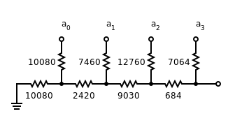
As I understood it, it is just set of resistor ladders like this one where you would "slide" and choose how much "steps" your ladders have ( how much resistance you have in series and in parallel ).
I found online logarithmic attenuator calculator which gave me not only values but also schematic for my project.
Logarithmic progression is for audio applications.
Those vales provided here are probably not the best, I just uploaded values I used in my setup.
Step 2: Channel Selector

I have 4 relays which activate channels. I already had board with relays from old preamp. Relays are activated by optocouplers and optocouplers are activated by arduino. You can use transistors instead of optocouplers.
I uploaded simple schematic how You can use optocoupler to control relay with arduino.
Step 3: Remote Controller

Since everything is controlled by arduino this was easy task. There is arduino library IRremote and lot of great tutorials on how to use them like this one https://learn.adafruit.com/using-an-infrared-library/hardware-needed.
For controller itself I reused old one. On link above You can learn how to read signal of old remote and re purpose it.
You can find code with explanations further down.
Step 4: Rotary Encoders

Rotary encoders are like limitless potentiometers, like those on your car's stereo. Actually they don't have anything in common with potentiometers except that you can put button on them and rotate. They contact ground and one of the pins when you rotate them and arduino reads that signal.
Once again, someone else did dirty job for me, I found arduino code for this task online! I will cover that also in some other step.
Step 5: PCB Layout


And now to put all that together. I used eagle cad for drawing schematic and pcb. You can find image and eagle project.
I decided to separate signal ground from "digital" that is why I have 2 polygons on top layer. I put mass as polygon and marks on top, and everything else is on bottom layer.
You can check attached fritzing breadboard scheme notes if you need more explanation how to connect peripheries to arduino.

Step 6: Code
I lost full version of code and this is from test phase but remote works, it just needs second decoder configured. I will recover it or rewrite it asap and upload it here.
EDIT: I found and uploaded full version of code.
Remote control
First import IRremote library and initialise it:
#include //import library before including from here
byte RECV_PIN = 11;
IRrecv irrecv(RECV_PIN); //initialization
decode_results results;
Inside setup()
irrecv.enableIRIn(); //enable ir in
inside loop()
if (irrecv.decode(&results)) //this checks if new data arrived
{ //inside check what button was pressed
if (results.value == 0xCC91D36E) { //volume down pressed
volcnt -=1; muxWrite(volcnt);
}
else if (results.value == 0xE936013E) { //volume up pressed
volcnt +=1; muxWrite(volcnt);
}
delay(100); //this is optional it just slows down volume change
irrecv.resume(); //wait for next data
}
Rotary encoders
No additional library is needed for encoders.
Setup
#define ENC_A 8
#define ENC_B 9
#define ENC_PORT PINB
Setup()
pinMode(ENC_A, INPUT);
pinMode(ENC_B, INPUT);
Loop()
tmpdata = read_encoder(); //read new state either -1 left turn, 0 no turn or 1 right turn
if( tmpdata ) { volcnt += tmpdata; muxWrite(volcnt); }
Read_encoder()
I found this function somewhere online
int8_t read_encoder(){
static int8_t enc_states[] = {0,-1,1,0,1,0,0,-1,-1,0,0,1,0,1,-1,0};
static uint8_t old_AB = 0;
old_AB <<= 2; //remember previous state old_AB |= ( ENC_PORT & 0x03 ); //add current state return ( enc_states[( old_AB & 0x0f )]);
}
Rest of code is controlling outputs, just writing LOW or HIGH on pins.
Attachments
Step 7: Final Toughts

This is V1.0 and if you have any ideas how to improve it, please share it with me!
I tested it and it works good. Not all steps are equal in attenuation but it is good enough, there are enough attenuation steps to find sweet spot. Only problem is that sometimes there is some noise for millisecond when relay switches on. Maybe I need better relays or something else (any ideas? :)).
For next version I will include relays for channel selection on pcb, but for that job I will need to shrink project since size of my board is on limit for freeware. I even have the idea to redraw all other boards (amp, buffer, PSUs, riaa...) I have now in my hifi on single one to remove all cables inside, but that will be in next instructable.
Price list:
| Part | Quantity | Price | Total |
| PCB | 90cm2 | 0.1$ | 9$ |
| Arduino | 1 | 3.5$ | 3.5$ |
| Resistors 0.6w 1% | 34 | 0.03$ | 1$ |
| Relays | 6 for atennuator + 4 for channels | 2.5$ | 25$ |
| Optocouplers | 10 | 0.15$ | 1.5$ |
| connectors | ~5$ | ||
| IR reciver | 1 | 0.7$ | 0.7$ |
| Rotary encoders | 2 | 2.5$ | 5$ |
| Power supply | ~10$ |
TOTAL: ~60$
This price is really rough. All prices are from local store in my city. If You don't need 4 channels or 64 atennuation steps You will get lower price. Respectively you can add more attenuation steps or input channels.

Participated in the
Automation Contest 2016

Participated in the
Sensors Contest 2016


