

Introduction: Arduino Portable EKG Monitor


Build a Portable EKG / ECG Monitor for less than 70U$!
What a great time it is to be a maker! The proliferation and popularity of Open source hardware and software, like the Arduino and Raspberry PI, have made it possible for makers to build all kinds of Gadgets. The by- product market of peripherals, like sensors, displays, and communication modules for these microcontrollers has also skyrocketed. You can now build devices to sense virtually any physical phenomena and display the results either locally on a attached display, or remotely via a Bluetooth or Wi-Fi module to a pc or smartphone. This instructable is a good example of how easy it is now to build a practical tool that can help improve your life by monitoring your heart. I hope it inspirers both beginning and experienced makers to keep on building.
According to Wikipedia the definition of EKG is:
"Electrocardiography (ECG or EKG *) is the process of recording the electrical activity of the heart over a period of time using electrodes placed on a patient's body. These electrodes detect the tiny electrical changes on the skin that arise from the heart muscle depolarizing during each heartbeat."
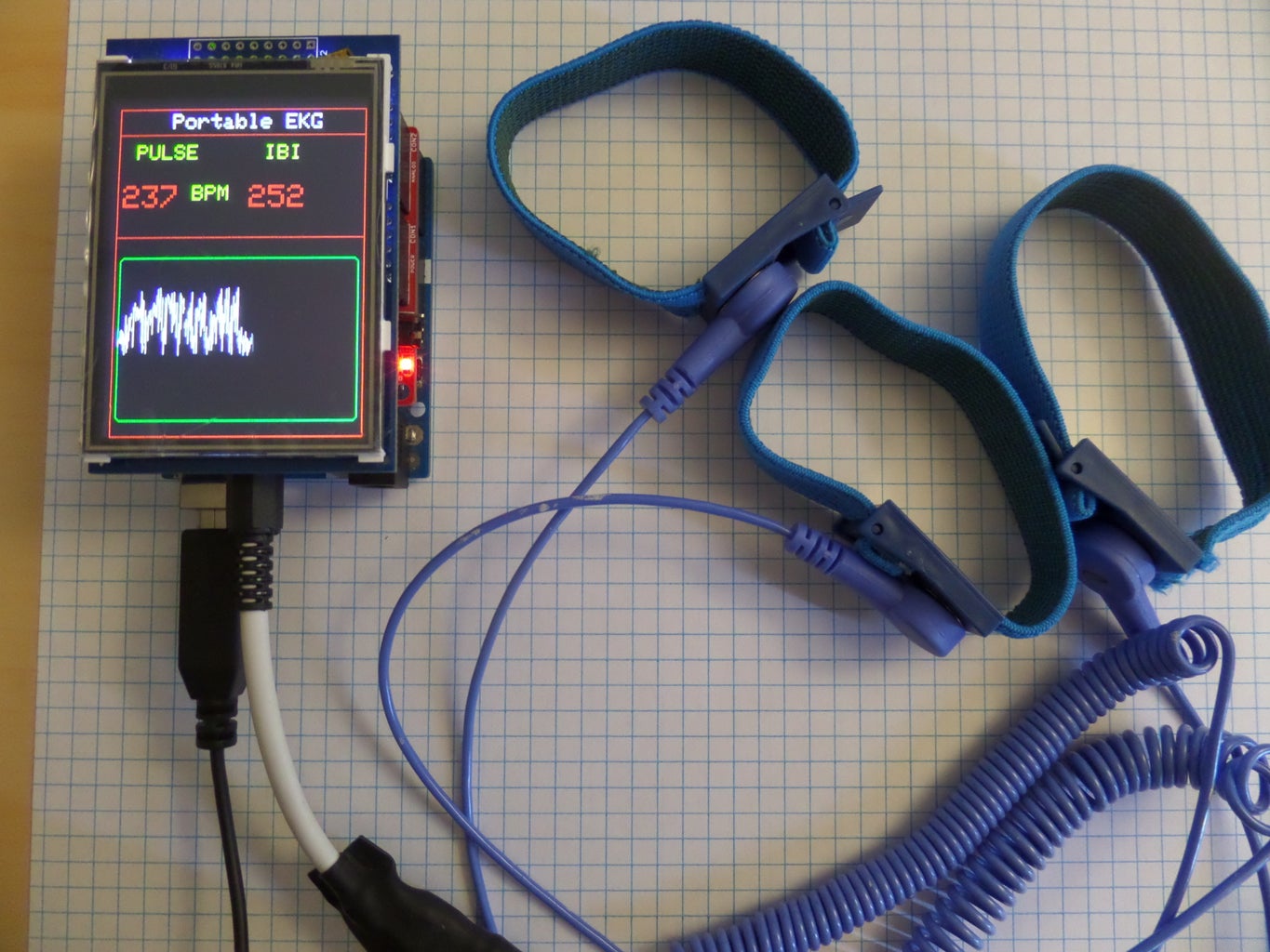
In this instructable, I will show you how to build a portable EKG, that fits the above description, using COTS (Common Of The Shelf) parts.
But before we start the build, and because this is a device that you attach to your body:
DISCLAMER: This project is not intended to be used as a medical device, it was conceived for educational purposes, use of this device for purposes other than those intended, is at your own risk.
That said, practical uses of this monitor are biofeedback - meditation aid, lie detector heart rate monitor , etc...
The main purpose of this instructable is to show you how you can use the Arduino to monitor your heart rate, and learn a little about how modern medicine can diagnose heart related health issues.
Most of the projects I make are for my own edification, but I also love to share my findings with others and hope that some of you enjoy learning by making as much as I do. My objective, is to make this instructables inexpensive, simple, practical, interesting and educational..
Step 1: Parts Needed /Construction


PARTS
You will need :
A PC with the Arduino IDE and a free USB port.
A USB cable to connect the Arduino to the PC
The GFX and TFT_LCD libraries from Adafruit
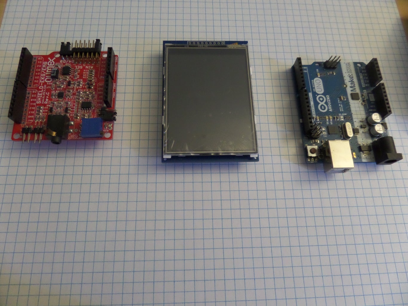
1 UNO R3 2.8 TFT Touch Screen with SD Card Socket for Arduino Board Module
1 OLIMEX SHIELD-EKG-EMG with SHIELD-EKG-EMG-PA EKG Arduino shield kit including lead
1 Battery holder with switch it can be a 9 v or 6v (4x1.5v AA) holder, to make it portable
* links are to parts in AMAZON, but you can get them from other providers.
CONSTRUCTION
Construction of the EKG Monitor is fairly simple. You just have to put the parts together. The heart (no pun intended!) of the project is the OLIMEX EKG Shield. This shield is the most expensive part of the project, but in my opinion, totally worth it's cost.
Once you have your parts in hand, just align the male pins on the OLIMEX shield with the female sockets on the Arduino and push with enough pressure to allow the pins to slide into the Arduino sockets. Do the same with the TFT LCD Shield and stack it on top of the OLIMEX Shield. You Are done with the Build..!!
HARDWARE DESCRIPTIONS
Before we go to the Software configuration, I want to briefly describe the hardware components, how they interact and what resources they use to perform the functions we desire.- for those who are interested. If not, feel free to go and configure the software in the next step. Below are summary descriptions of the three boards used, summarized from information found in the internet.
The first component is the Arduino Micro controller. I like to think of the Arduino as a set of pins that I can control and configure (through software instructions) to do my bidding. The pins are divided into three categories: Digital pins, Analog pins, and Support pins.
The Digital pins:
Each of the 14 digital pins on the Arduino Uno can be used as an input or output, using pinMode(),digitalWrite(), and digitalRead() functions. They operate at 5 volts. Each pin can provide or receive a maximum of 40 mA and have an internal pull-up resistor (disconnected by default) of 20-50 KOhms. In addition, some pins have specialized functions:
Serial: pins 0 (RX) and 1 (TX) are used to receive (RX) and transmit (TX) TTL serial data. These pins are also connected to the corresponding pins of the ATmega8U2 USB-to-TTL Serial chip( if you use these pins to interface with a sensor or output device, you will need to disconnect the device before downloading a program or it will probably interfere with the download).
External Interrupts: pins 2 and 3. These pins can also be configured to trigger an interrupt on a low value, a leading or falling edge, or a change in value. See the attachInterrupt() function for details.
PWM pins: 3, 5, 6, 9, 10, and 11. can also Provide 8-bit PWM (Pulse Width Modulation) output with the analogWrite() function (usually used to control motor speed).
SPI: 10 (SS), 11 (MOSI), 12 (MISO), 13 (SCK). These pins support SPI communication using the SPI library.
LED: 13. There is a built-in LED connected to digital pin 13. When the pin is HIGH value, the LED is on, when the pin is LOW, it’s off.
The analog pins
The Uno has 6 analog inputs, labeled A0 through A5, each of which can provide 10 bits of analog to digital conversion resolution (i.e. 1024 different values). By default they measure from ground to 5 volts, though it is possible to change the upper end of the range using the AREF pin and the analogReference() function.
in addition, some of the Analog pins also have specialized functionality: TWI(Two Wire Interface): A4 or SDA pin and A5 or SCL pin. Support TWI communication using the Wire library. (Note: you can also use the analog pins as digital pins)
There are a couple of other Support pins on the board: Reset; Bring this line LOW to reset the microcontroller. Typically used to add a reset button to shields which block the one on the board.. Last but not least are the Power pins that can provide Ground and 5 volt as well as 3.3 volt power to your project.
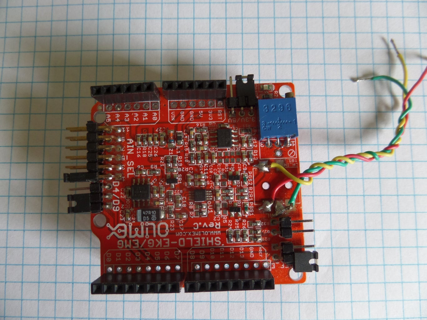
The Olimex EKG Shield is basically an instrumentation amplifier followed by an operational amplifier and a low pass filter. The shield has pass through pin sockets so you can piggy back another shield on top of it. the output is jumper configurable to any of the Arduino analog pins (A0 to A5). Below is a summarized but more detailed explanation from the Olimex web site:
The EKG/EMG shield allows the Arduino to capture Electrocardiography and /or Electromyography signals. The shield opens new possibilities to experiment with biofeedback. With this shield, you can monitor your heartbeat, log your pulse, and /or recognize gestures by monitoring and analyzing muscle activity.
The EKG-EMG SHIELD converts an analog differential signal (the ECG/EMG bio potentials generated by muscles), attached to its CH1_IN+/CH1_IN- inputs, into a single stream of amplified and filtered analog signal at the output. Since the output signal is analog, it has to be fed to one of the five Arduino analog inputs to be discretized (analog to digital conversion) further with aim to give the option of digital processing. Typically, this is done via dedicated ADC embedded in the MCU of the base board (like: OLIMEXINO-328, OLIMEXINO-32U4, OLIMEXINO-STM32, etc). In the demo example we have provided, "ShieldEkgEmgDemo.ino", we have used 10-bit ADC with 256Hz sampling rate. SHIELD-EKG-EMG’s total gain is the product of the gains of each stage: Instrumental Amplifier(G1=10), OPamp with adjustable gain (G2=6..101) and 3rd order "Butterworth" filter (G3=3.56). Then, the Gtotal = G1*G2*G3 = 10*(6..101)*3.56. By default, the G2 gain is set to approximately 80. So, Gtotal = 10*(~80)*3.56 ~ 2848. Vmaxanalog = 3.0V/2848 ~ 1mV Note that the 3rd order "Butterworth" filter's cutoff frequency is set to fc = 40Hz.
Description:
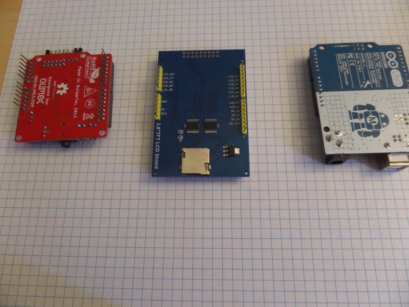
2.8" TFT LCD Display is an LCD touch screen module. It has a 40 pin interface and SD card / Flash reader built in. It is a powerful, multifunctional module .The Screen includes a ILI9325 controller, that supports 8/16bit data interfacing ,it is easy to drive by micro controllers like Arduino, STM32 ,AVR and 8051. It contains an integrated touch controller. The touch IC is XPT2046 , and touch interface pins are included in the 40 pin breakout.
Features
: •240374PQ •262K color •240*320 •2.8 inch •Wide viewing angle •ILI9325:240 RGB x 320 TFT Driver •Integrated Power, Gate and Source Driver With RAM •XPT2046-WIRE TOUCH,WIRE TOUCH, UP TO 125kHz CONVERSION RATE, SERIAL INTERFACE •Voltage type: 5v or 3v voltage input voltage, input is selectable. but Because TFT can only work under 3.3 Volts when the input voltage VIN is 5 Volts, it needs to be converted to 3.3 Volts by the onboard voltage regulator IC that steps down the 5V to 3.3V. When the input voltage is 3.3 Volts, you need to use a jumper to short J2 , to bypass the voltage regulator IC and power the screen directly Note: the factory default for the TFT module is 5 Volts power supply. The on board SD holder is set to work on SPI mode.
Component interaction and resources.
Now that we are familiar with the basic parts, lets describe how they interact with each other :
The OLIMEX shield uses only one Arduino resource, the Analog 5 input (A5).The amplified and filtered signal from your heart is fed to this input to be digitized by the Arduino Analog to digital converter. You can select what Arduino analog input you want to feed the signal to with a jumper, but the analog 5 (A5) is the only input not used by the TFT LCD display.
The TFT Touch screen display uses digital pins (D2 to D13) plus the analog pins (A0 to A4) to manage the display output, the touch screen functions, and the SD card. this leaves only 3 free I/O pins on the Arduino; the A5 analog input (which we will use to feed the signal that comes from the OLIMEX shield) and the TX (D1) and RX(D0) digital I/O pins that are used for communication.
As you can see, all the pins in our Arduino are used up!!

Step 2: The Sketch
Before you can run the sketch, you need to make sure you have the required libraries installed. I included a .zip file that contains the libraries. Download the file, decompress, and copy the to folders containing the libraries' to the library sub folder in the Arduino folder.
Before you install the sketch for the EKG, you should check to make sure that the libraries are properly installed by running some of the examples included with the library; You can do this by selecting examples on the File dropdown menu and then selecting the Adafruit_TFTLCD option and then the graphicstest example. (note: if you are using the same module I bought from amazon, use the breakout examples and not the shield examples).
If you are having difficulties getting the TFT Screen to work check out this instructable by dmainmon who did an excellent job explaining how to get it working.
If you have successfully tested the modules, you can now download the sketch and upload it to the Arduino.
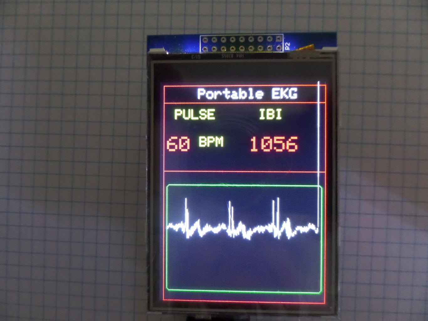
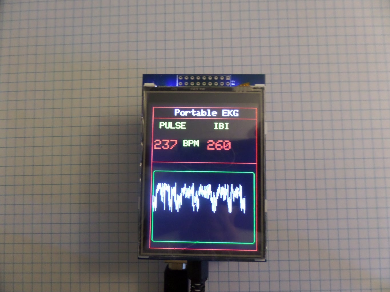
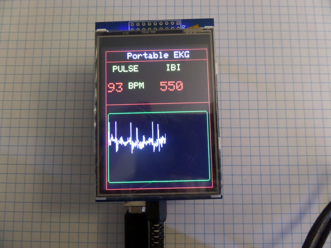
Because I'm not the kind of guy that tries to re-invent the wheel, I used code that came from the PulseSensor.com website. I didn't change the portions that calculate the pulse Rate and IBI and used them to supply the data to the TFT Display. I added the graphing portion to display the EKG Waveform. By the way you can use the OLIMEX EKG shield with the electrodes to display your EKG using the processing sketches from PulseSensor, and the most excellent instructable by dmainmon.
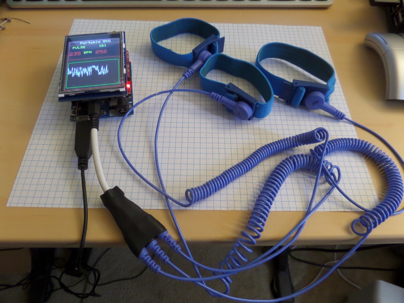
Once you have the sketch uploaded to the Arduino modules, put the electrode straps on your left and right wrists (labeled L and R), and the last electrode(labeled D) to your right ankle. sit down in a comfortable chair as far away from EMF noise as possible and start monitoring your heart!!

Step 3: Going Further
Now that you have built the EKG Monitor and Tested it on yourself, and some of your family members, you must be thinking "what else can I Do with it?" well here are some ideas :
- Use it as a meditation device. see how much you can lower your heart rate through meditation.
- What do emotions do to your heart rate? does anger speed up your heart rate?, change your IBI? what about Fear? or Love?.
- Does a broken heart really break your heart?
- Does Heart Burn due something to your heart rate?
- Does the speed of my heart rate change my perception of time?
- log my EKG and view changes over time (using the Built in SD Card, and transferring data to a PC for analysis)
- Can I monitor the heart rate of my Dog or any other animal?
- Do plants have a heart, and if they do, can I monitor it?
Note: you may need to Modify your electrode leads, or make new electrode leads using a 1/4 inch stereo male jack and jumper wires, to perform some of the experiments.
Step 4: Bonus: Data Logger and Differential Amp DVM Apps!


These are still work in progress , but I decided to share them with you, before I forget.
DATA Logger
The TFT Display module includes a SD Card Reader that you can use to log data that you capture with the OLIMEX shield. You can use the captured data for display or analysis off line on excel or some other PC app for data analysis. The data is stored in comma delimited format. I still need to add a start and pause button and refine the display and UI, but I included some screenshot pics of how to import the data to excel and then graph the data. you will need a Micro SD card and your PC needs to have a SD Card reader to do this.
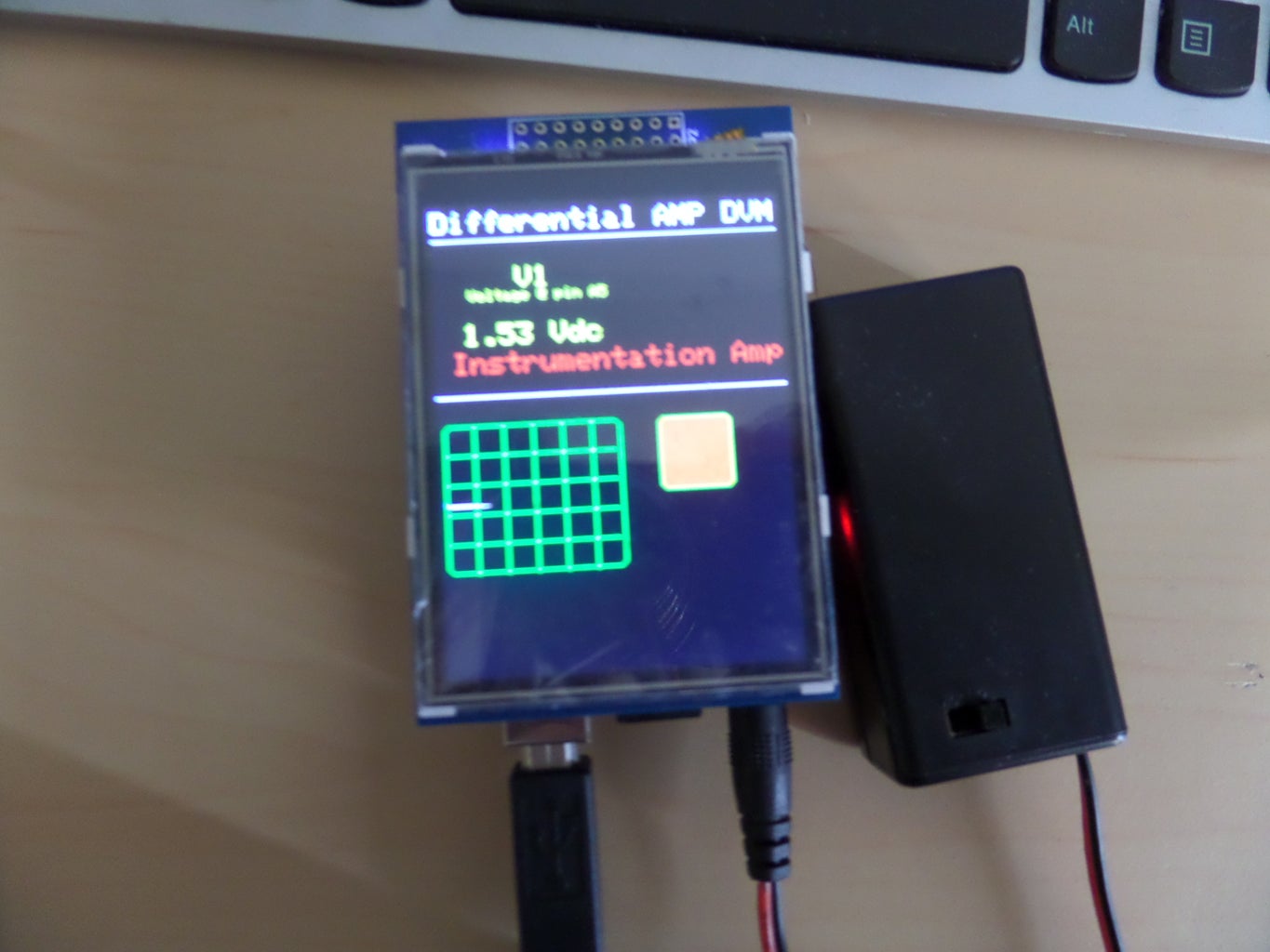
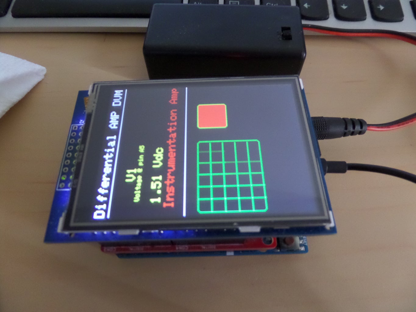
Differential Amp DVM
This sketch is a modified version of my DC DVM instructable adapted to use with the OLIMEX Shield. also a work in progress. I Plan to include some touch screen functionality and integrate both sketches into One, when I get some time.

Participated in the
Invention Challenge 2017

Participated in the
Explore Science Contest 2017


