

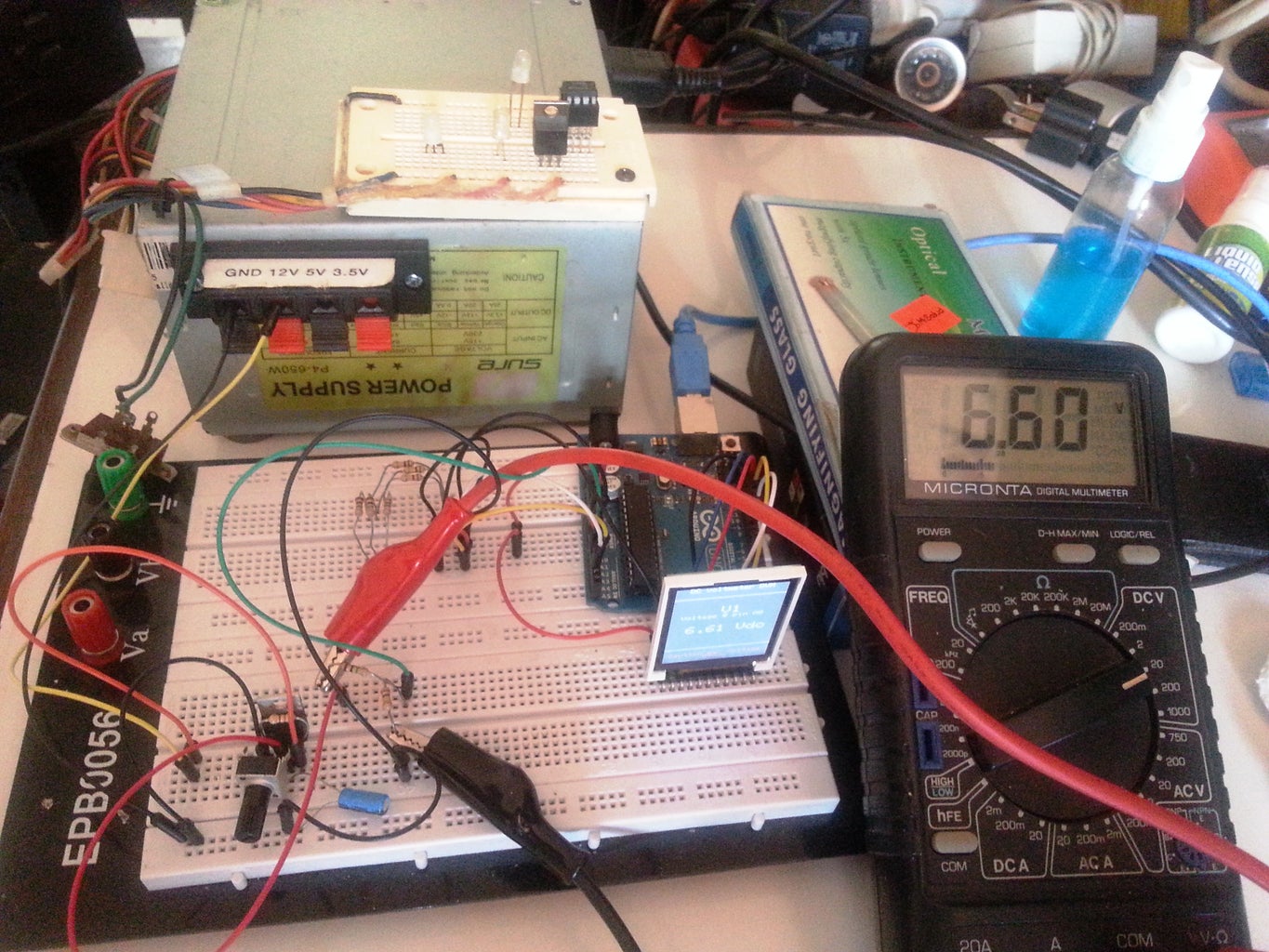
Introduction: Make a Mini Arduino Programmable 4 Channel DC-DVM


This Instructable will teach you how to use the Arduino Analog ports.
Digital Voltmeters (DVMs) are a special case of Analog to Digital converters- A/DCs.- they measure voltage - and are usually a function of a general purpose instrument called a Digital Multimeter( DMMs), commonly used to measure voltages in labs and in the field. DMMs display the measured voltage using LCDs or LEDs to display the result in a floating point format. They are an instrument of choice for voltage measurements in all kinds of situations. This instructable will show you how to use the Arduino as a DC DVM (Direct Current Digital Volt Meter).
We will be using the Arduino analog inputs to measure DC voltages between 0 and 5V and displaying the values on a TFT LCD Color display.
I used the Sainsmart Arduino Nano and the Official Arduino UNO R3 to see if there are any differences.
The voltage ranges that the Arduino can measure can be easily expanded by using two resistors to create a voltage divider.
The voltage divider literally scales down the voltage being measured so it is within the range of the Arduino analog inputs(i.e.. 0 to 5 volts).
You can then program the Arduino sketch to calculate the actual voltages being measured by multiplying the input by the scaled factor.
This will allow us to measure voltages greater than 5V DC, the maximum DC voltage we can measure safely is ~50 VDC with the parts used in this instructable, but can be modified to suit your needs..
Step 1: What You Will Need: Parts List


Total cost is around $35 dollars!
- An Arduino ( I Used the Sainsmart Nano Clone, ($13.99) and an UNO R3, but I think any one will do)
- A PC with the arduino IDE and a free USB port.
- A USB cable for your Arduino
- A Sainsmart 1.8" TFT COLOR LCD($12.99) Display
- 4 x 1 Mega Ohm Resistors (Brown ,Black, Green) 1 for each channel
- 4 x 100 Kilo Ohm Resistors(Brown, Black, Yellow) 1 for each channel
- 4 5.1 volt zener diodes (optional|) for added protection to the Arduino analog inputs
- Jumper cables, lots of them, different sizes and colors
- Solderless Breadboard (I'm using. My RadioShack electronic experimenters lab breadboard)
- A multimeter and /or voltage reference to calibrate the DVM outputs
Step 2: DVM BASIC PRINCIPLES

Before we begin to put the project together, let's review some basic principles and precautions concerning voltage measurements with a DVM.
Accuracy and precision
Our DVM will not be as accurate or precise as a commercialy available unit, but it wil certainly be more flexible.
In order to make the readings as accurate as possible, we must consider two things: the input resolution, and the calibration. Input resolution depends on the Arduinos analog input A/D converter, which is 10 bits on the Arduino uno and nano. Calibration will depend on the quality of the components used and the references used to calibrate the measurments.
Input Impedance
Comercial digital multimeters that measure DC voltage will usually have a very high input impedance of 10MΩ or greater.(i.e- the resistance between the two multimeter test probes is 10MΩ or more.)
A high input impedance for a voltmeter is needed so that the voltmeter will not affect the value of the circuit being measured.
If a voltmeter has a low input impedance, it can possibly change the voltage being measured and give you incorrect readings..
There is also a drawback, however, to having a high input impedance; The test probes are more prone to pick up electromagnetic interference (EMI) which can also offset your measurements and display "phantom" readings.
Although a high input impedance is desirable, the voltage divider circuit we will be using, will give our voltmeter an input impedance of about 1MΩ, which is acceptable for most low voltage measurements and low impedance circuits usually built by electronic hobbyists.
Voltage Divider Circuit
We will use two resistors in series that will scale down the input voltage to a range within the safe boundaries of the Arduino analog input specs. The basic voltage divider equation is:
V out = V in*R b /( R a + R b )
If:
R a = 1MΩ
R b = 100KΩ
V out = 5V (the maximum voltage for the arduino analog input pins)
then;
V in = 55V (the maximum voltage that can be measured safely)
The circuit we will use, will divide the input voltage by 11; (100K / (100K + 1M))=(100 /1100)=(1 /11)
Common Ground constraint
Most comercial DVMS allow you to measure the voltage across any component, not only from a ground reference. Our Arduino based voltmeter cannot do that, it can only measure from a ground reference because the Arduino GND pin is used as the negative or common (COM) test probe lead of a standard multimeter,and should be connected to the ground of the circuit under test.
Input Protection
The resistor values we are using provide some overvoltage protection when measuring low voltages and up to around 55 volts. To protect the Arduino from an accidental overvoltage(>55VDC), we can, optionally, use 5.1 volt zener diodes in parallel with the 100KΩ resistors, This will provide added protection to the Arduino analog input pins.
Maximum voltage rating
As previously explained, the point on the resistor divider network connected to the the Arduino analog input pin is equal to the input voltage divided by 11 ( 55V ÷ 11 = 5V). The maximum voltage that can be safely measured is 55 Volts, the Arduino analog pin will be at its maximum voltage of 5V. Caution!!! do not try to measure voltages higher than 55 Volts or you may damage your Arduino
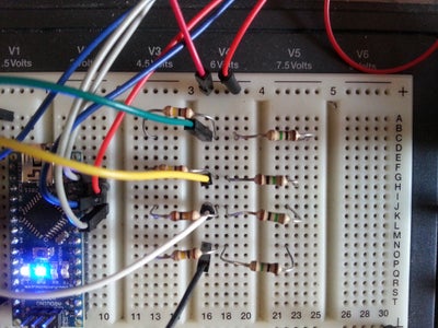
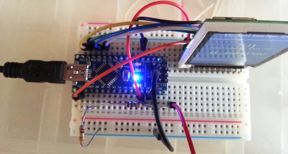
Step 3: Circuit Construction


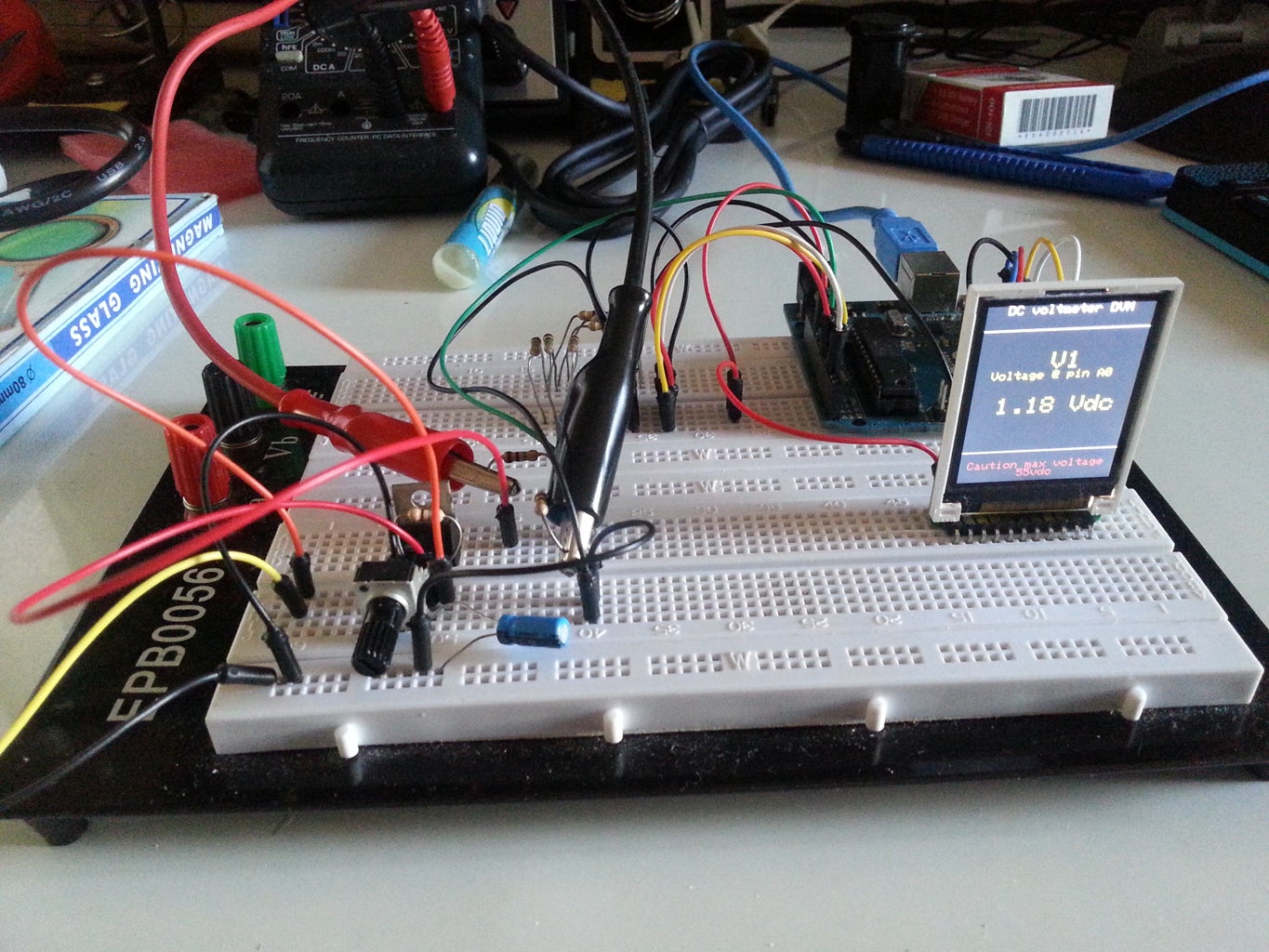
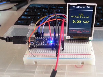
We will start by building one voltage divider and connecting it to the Arduino, test the circuit with a simple sketch, and proceed to building the rest of the circuits.
Once we have the inputs working, we will install the 1.8" TFT LCD Color display and write a sketch to display the input measurement on it.
We will then explore several software and hardware options to improve or customize the DVM.
So lets start by building the voltage divider on the breadboard and connecting it to pin A0 of the Arduino.
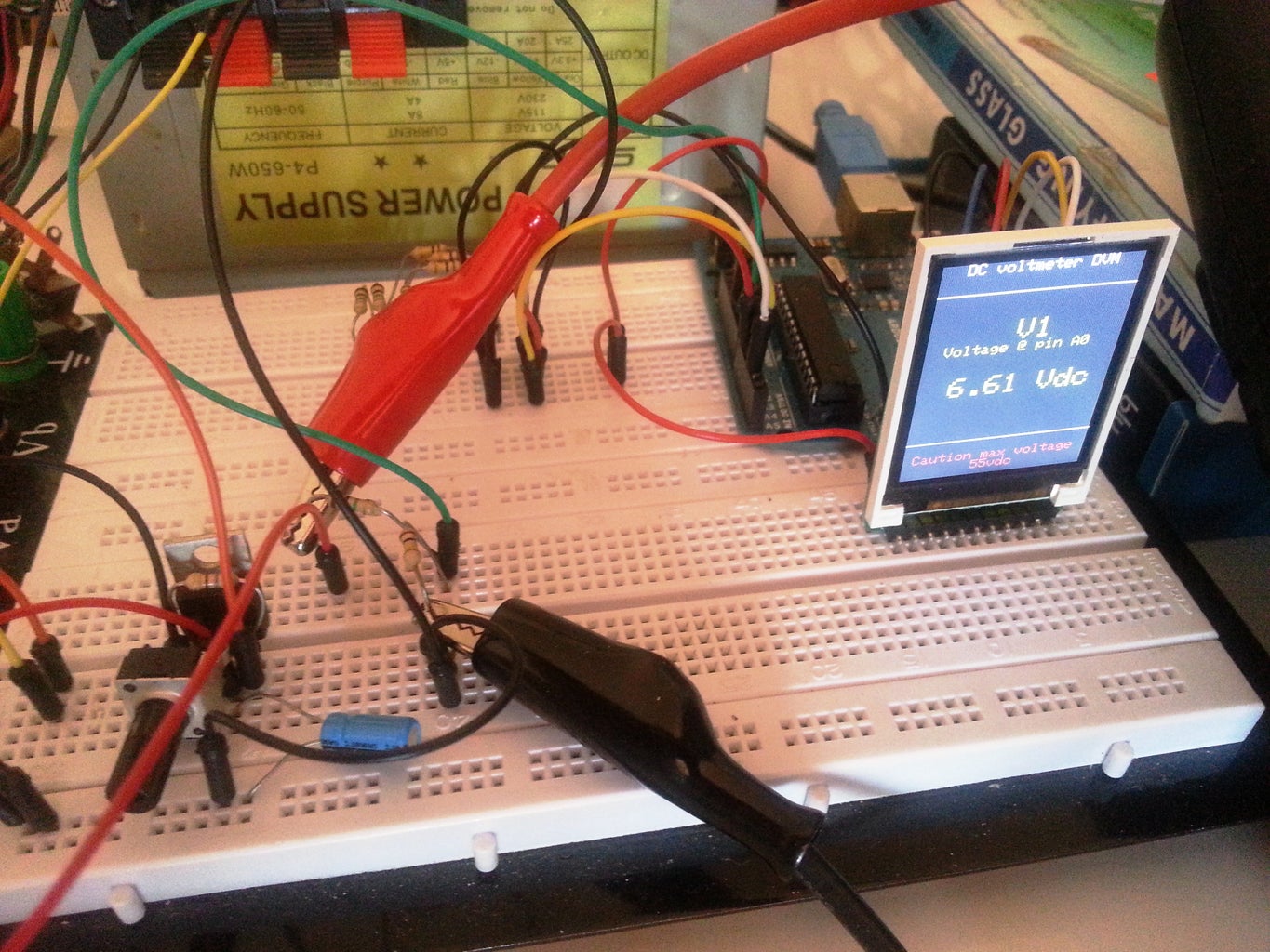
Look at the circuit diagram and the other pictures to guide you with the steps.
Once the circuit is put together, plug the Arduino to the USB port on your PC, and upload the following test sketch which will display the voltage connected to the free 1Meg resistor leg via the serial monitor.
Just copy and paste the following sketch to the Arduino IDE.
// -----------------Sketch Start-----------------------------
/* -----------------------------------------------------------
Program: SERIAL DVM
Description: DC voltmeter with voltage displayed on serial monitor
No Color TFT LCD yet!
Hardware: Arduino NANO or Uno with voltage divider on A0.
Software: Written and Developed using Arduino 1.0.3 software
Date:
Author:
--------------------------------------------------------------*/
// voltage divider calibration values
#define Dv1 11
// ADC reference voltage / calibration value
#define VREF 5
float V1 = {0.00};
void setup()
{
Serial.begin(9600);
}
void loop()
{
V1= analogRead(0);
Serial.print(" Voltage @ pin A0 ");
Serial.println((((V1*VREF) / 1023)) * Dv1, 2);
}
// -----------------Sketch End-----------------------------
Let's review what's happening;
The Atmega controller used for the Arduino contains an on-board 6 channel analog-to-digital (A/D) converter. The converter has 10 bit resolution, which returns an integer from 0 to 1023 (210=1024, 0 counts, so it's 1023 steps) for the value of 0 to 5 volts.
We want to convert the A/D returned value to the actual voltage that we are measuring.
We need to multiply the result by 5 and divide by 1023 to adjust the value returned by the 10 bit A/D Converter.
We are also dividing the voltage by 11 with the voltage divider, so the voltage we are measuring ( and we want to see on the display), has to be multiplied by 11 to compensate for the division.
We do that with the followimg formula:
Vout=((Vin*(5/1023))*11).
the code for this is:
Serial.println((((V1*VREF) / 1023)) * Dv1, 2);
We multiply by 5(VREF)and divide by 1023 to convert the A/D output into a scale between O and 5,then we multiply by 11(Dv1) to compensate for the voltage divider . The reason we are using variables for the divider and voltage values, is that these values will change when we calibrate the DVM. The "2" at the end of the formula defines how many digits to show after the decimal.
If you got the program to load correctly, open the serial monitor by clicking on the magnifying icon in the upper righthand corner of the arduino IDE, you should see data flowing. Using a jumper wire, try connecting the free leg of the 1Meg resistor to the GND Pin first and then to the 5V pin . You should see the reading change from 0 to 5v.
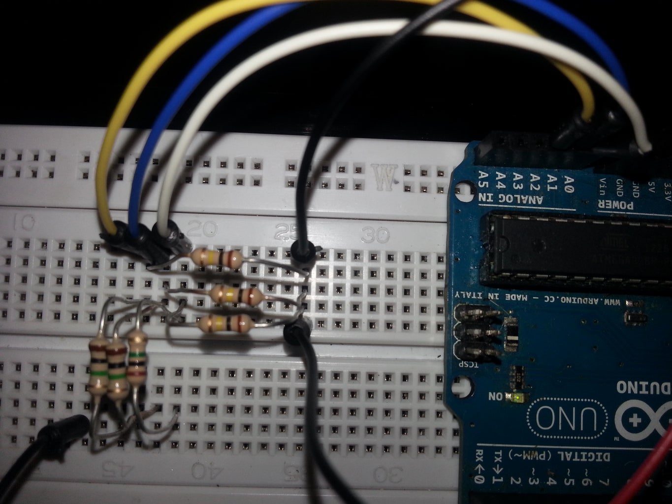
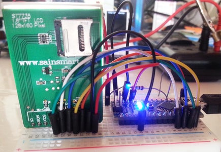
Now we just have to repeat what we did for the first channel three more times to have a 4 channel DVM, but before we do that, let's connect our TFT COLOR LCD DISPLAY to the Arduino. You will need 7 jumper wires to do this:
Connect the following with the jumpers
TFT LCD. Arduino
VCC 5V
GND Gnd
SCL 13
SDA 11
CS 10
RS/DC 9
RES 8
Note:
Unlike my other instructables, we will be using the high speed SPI Interface to drive the display so the jumper wiring is different. Again, check out the pictures to guide you if your not sure how to wire it up.
You will need to install two libraries to use the display:
Adafruit_GFX.h The Core graphics library
Adafruit_ST7735.h The Hardware-specific library
Download the libraries and copy them to the Arduino library folder.
Copy and paste the sketch below to the Arduino IDE. The sketch DVM code is the same, but with the addition of code to display the voltage on A0 on the LCD Display.
Compile and Upload the sketch to the Arduino.
// -----------------Sketch Start-----------------------------
/*-----------------------------------------------------------
Program: TFTLCDDVM
Description: DC voltmeter with voltage displayed
on Color TFT LCD to 2 decimal places
Hardware: Arduino NANO with voltage divider on A0.
TFT LCD connected
Software: Developed using Arduino 1.0.3 software
Date: 10 March 2014
Author: johnag
--------------------------------------------------------------*/
#define sclk 13
#define mosi 11
#define cs 10
#define dc 9
#define rst 8 // reset
#include <Adafruit_GFX.h> // Core graphics library
#include <Adafruit_ST7735.h> // Hardware-specific library
#include <SPI.h>
Adafruit_ST7735 tft = Adafruit_ST7735(cs, dc, rst);
// voltage divider calibration value
#define Dv1 11
// ADC reference voltage
#define VREF 5
float V1 = {0.00};
void setup()
{
Serial.begin(9600);
tft.initR(INITR_BLACKTAB); // initialize a ST7735S chip, black tab
tft.fillScreen(ST7735_BLACK); // clear screen
tft.setTextColor(ST7735_WHITE);
tft.setTextSize(1);
tft.setCursor(10,0);
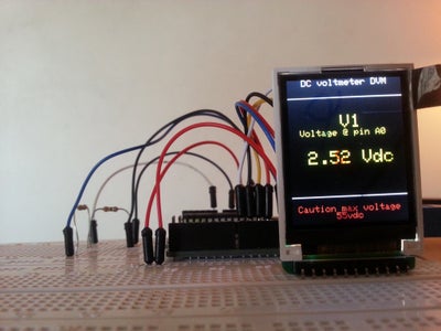
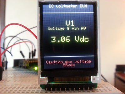
tft.println(" DC voltmeter DVM");
tft.setTextColor(ST7735_RED);
tft.setCursor(0,140);
tft.println(" Caution max voltage 55vdc");
}
void loop()
{
V1= analogRead(0);
tft.drawLine(0, 20, tft.width()-1, 20, ST7735_WHITE);
tft.drawLine(0, 130, tft.width()-1, 130, ST7735_WHITE);
tft.setTextColor(ST7735_YELLOW,ST7735_BLACK);
tft.setTextSize(2);
// voltage 1 (pin A0)
// voltage is multiplied by the resistor network
// division factor to calculate the actual voltage
tft.setCursor(45, 40);
tft.println(" V1 ");
tft.setTextSize(1);
tft.println(" Voltage @ pin A0 ");
tft.setCursor(20, 80);
tft.setTextSize(2);
Serial.print(" Voltage @ pin A0 ");
Serial.println((((V1*VREF) / 1023)) * Dv1, 2);
tft.print((((V1*VREF) / 1023)) * Dv1, 2);
tft.print(" Vdc ");
}
//---------------Sketch End----------------------------------------
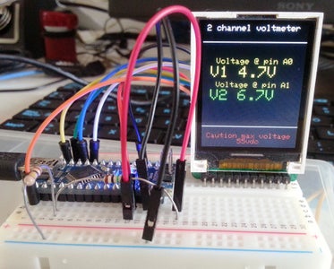
Step 4: 2 Channel DVM CODE
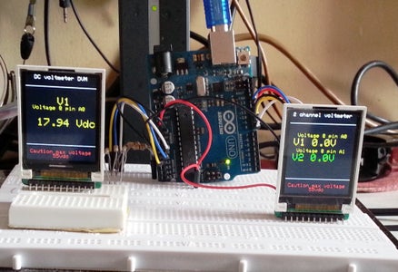
Below is the sketch for a 2 channel DVM copy and paste it to the Arduino IDE. I will leave the code for the 4 channel DVM for after were done with the calibration.
//---------------------------2channel DVM start---------------------
/*--------------------------------------------------------------------
Program: voltmeter_LCD
Description: 2 channel DC voltmeter with voltages displayed
on Color TFT LCD to 1 decimal place
Hardware: Arduino NANO with voltage dividers on A0 and A1
TFT LCD connected
Software: Developed using Arduino 1.0.3 software
Date: 10 March 2014
Author:
--------------------------------------------------------------*/
#define sclk 13
#define mosi 11
#define cs 10
#define dc 9
#define rst 8 // reset
#include <Adafruit_GFX.h> // Core graphics library
#include <Adafruit_ST7735.h> // Hardware-specific library
#include <SPI.h>
Adafruit_ST7735 tft = Adafruit_ST7735(cs, dc, rst);
// voltage divider calibration values
#define Dv1 11.00 // calculated by measuring voltage at resistor junction
#define Dv2 11.25
// ADC reference voltage / calibration value
#define VREF 4.9
float V1 = {0.0};
float V2 = {0.0};
void setup()
{
tft.initR(INITR_BLACKTAB); // initialize a ST7735S chip, black tab
tft.fillScreen(ST7735_BLACK); // clear screen
tft.setTextColor(ST7735_WHITE);
tft.setTextSize(1);
tft.setCursor(5,0);
tft.println("2 channel voltmeter");
tft.setTextColor(ST7735_RED);
tft.setCursor(0,140);
tft.println(" Caution max voltage 55vdc");
}
void loop()
{
V1= analogRead(A0);
V2= analogRead(A1);
tft.drawLine(0, 20, tft.width()-1, 20, ST7735_WHITE);
tft.drawLine(0, 130, tft.width()-1, 130, ST7735_WHITE);
tft.setTextColor(ST7735_YELLOW,ST7735_BLACK);
// voltage 1 (pin A0)
tft.setCursor(5, 40);
tft.setTextSize(1);
tft.println(" Voltage @ pin A0 ");
tft.setTextSize(2);
tft.setCursor(10, 50);
tft.print("V1 ");
tft.print((((V1*VREF) / 1023)) * Dv1, 1);
tft.print("V ");
// voltage 2 (pin A1)
tft.setCursor(5, 70);
tft.setTextSize(1);
tft.println(" Voltage @ pin A1 ");
tft.setTextSize(2);
tft.setTextColor(ST7735_GREEN,ST7735_BLACK);
tft.setCursor(10, 80);
tft.print("V2 ");
tft.print((((V2*VREF) / 1023))* Dv2, 1);
tft.print("V ");
}
//---------------------------2channel DVM END------------------
Step 5: Calibration
Steps for calibration:
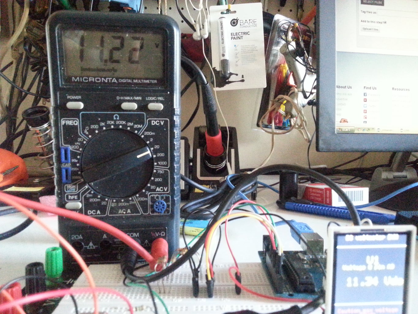
- Measure the voltage at the 5v pin in the Arduino with your multimeter, and use that number in the code as the VREF value. for example, if you measured 5.0v then the line in the sketch that defines VREF should be #define VREF 5.0.
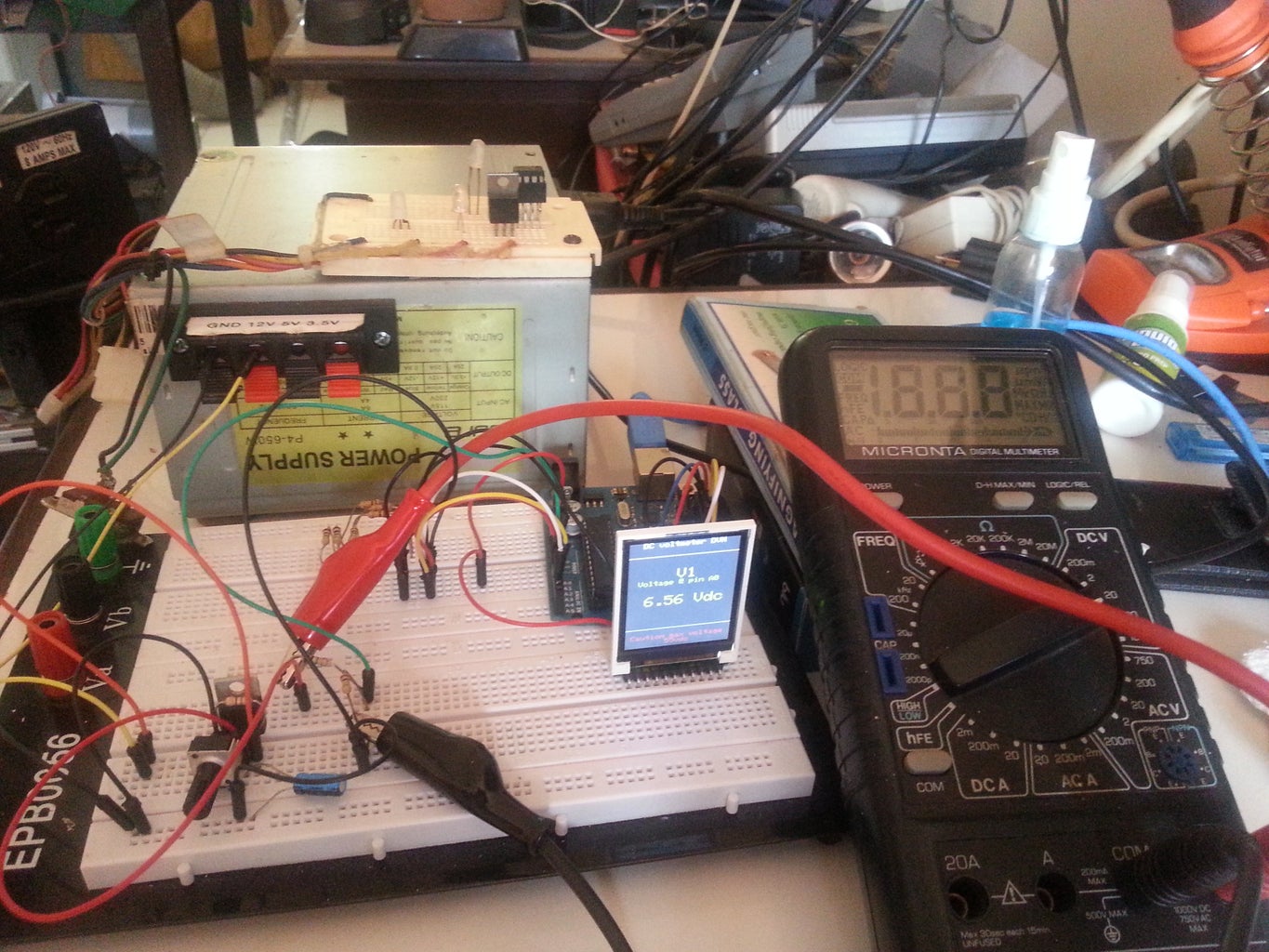
- On your voltage divider circuit, plug the free leg on the 1meg resistor to the 5v pin of your Arduino, and measure the voltage across the entire voltage divider and then the voltage across the 100 k resistor. (first from GND to the 5v then from GND to the resistor junction point, across the 100k resistor). Now divide the two voltages, for examle, I got 5.0 for the voltage from GND to 5v and 0.46v for the voltage across the 100k resistor so I divide 5 by 0.46: 5/0.46=10.869
- Place that value in the Dv1 definition line: #define Dv1 10.869.
- Upload the sketch and see if the reading on your display matches the reading on your multimeter.
- Repeat the steps for all the voltage dividers and change the values accordingly.
Step 6: Sampling, Averaging, and Displaying
OK, so we calibrated the DVM, but the readings still seem a little unstable and slightly offset. There's still something we can do about that. Instead of just displaying the measured input, why don't we take several samples, add them together, and divide the sum by the number of samples taken. This will give us an average of the values in the input, and provide us with a more stable reading. Lets do that using the whileloop.
The sketch below uses sampling and averaging to improve the displayed values. Copy and Paste it to the Arduino IDE and compile and load it.
// -----------------Sketch Start-----------------------------
/*--------------------------------------------------------------
Program: 1 channel DVM with Sampling
Description: Reads value on analog input A0 and calculates
the voltage with a voltage divider
network on pin A0 that divides by 10.195 and a reference voltage of 5.0v.
Hardware: Arduinonano or Uno with voltage divider on A0.
Software: Developed using Arduino 1.0.3 software
Should be compatible with Arduino 1.0 +
Date: March 25 2014
Author:
--------------------------------------------------------------*/
#define NUMSAMP 100 // number of samples to take before averaging and displaying
#define sclk 13
#define mosi 11
#define cs 10
#define dc 9
#define rst 8 // reset
#define Dv1 10.915 // Voltage divider value
#define VREF 5.0 // Voltage measured @Arduino 5V pin
#include <Adafruit_GFX.h> // Core graphics library
#include <Adafruit_ST7735.h> // Hardware-specific library
#include <SPI.h>
Adafruit_ST7735 tft = Adafruit_ST7735(cs, dc, rst);
int sum = 0; // Sum of samples taken
unsigned char Scount = 0; // Current sample number
float AVvolts = 0.0; // Calculated Average voltage
void setup()
{ // Setup display and print static items
tft.initR(INITR_BLACKTAB); // initialize a ST7735S chip, black tab
tft.fillScreen(ST7735_BLACK); // clear screen
tft.setTextColor(ST7735_WHITE);
tft.setTextSize(1);
tft.setCursor(10,0);
tft.println(" DC voltmeter DVM");
tft.println(" ");
tft.println(" ");
tft.print(" Voltage @ pin A0 ");
tft.setTextColor(ST7735_RED);
tft.setCursor(0,140);
tft.println(" Caution max voltage 55vdc");
}
void loop()
{
// take a number of analog samples and add them up
while (Scount < NUMSAMP) {
sum += analogRead(A0); // read and add the samples
Scount++; //increment the sample count
delay(10); //Wait 10 mS before reading next sample
}
AVvolts = ((float)sum / (float)NUMSAMP * VREF ) / 1023; // calculate average voltage
// Display the calculated Average voltage
tft.setTextColor(ST7735_YELLOW,ST7735_BLACK);
tft.setTextSize(2);
tft.setCursor(45, 50);
tft.println(" V1 ");
tft.setCursor(10, 80);
tft.setTextSize(2);
tft.print(AVvolts * Dv1);
tft.println(" Vdc ");
Scount = 0;
sum = 0;
}
// -----------------Sketch End-----------------------------
Step 7: The Programs in Programmable


There are 10 kinds of people, those who know binary and those who don't.
So far, we have learned how to put together an Arduino and add voltage dividers to condition the analog input signal (voltage) by reducing the signal to a level that is within the parameters of the Arduino specifications. We then compiled and uploaded some sketches that read the signals and displayed them on the serial monitor and the TFT LCD Display. Now it's up to you to study the code and continue the work. I am including the code for the oter sketches that will run with the hardware we put together.
/*--------------------------------------------------------------
Program: 1 channel DVM with Sampling
Description: Reads value on analog input A0 and calculates voltage assuming
there is a voltage divider on pin A0 that divides by 10.195
Hardware: Arduino NANO or UNO with voltage divider on A0.
Software: Written using Arduino 1.0.3 IDE
Date: March 25 2014
Author:
--------------------------------------------------------------*/
// number of analog samples to take per reading
#define NSAMP 100
#define sclk 13
#define mosi 11
#define cs 10
#define dc 9
#define rst 8 // reset
#include // Core graphics library
#include // Hardware-specific library
#include
Adafruit_ST7735 tft = Adafruit_ST7735(cs, dc, rst);
int sum = 0; // sum of samples taken
unsigned char Scount = 0; // current sample number
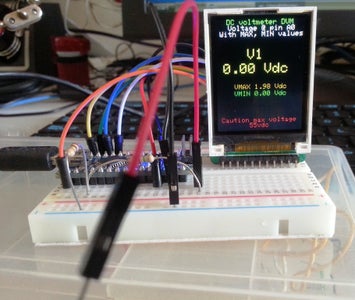
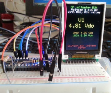
float V1 = 0.00; // calculated Average voltage
float VMAX = 0.00;
float VMIN = 100.00;
float val = 0.00;
float VREF = 5.0;
float Dv1 = 10.935;
void setup()
{
tft.initR(INITR_BLACKTAB); // initialize a ST7735S chip, black tab
tft.fillScreen(ST7735_BLACK); // clear screen
tft.setTextColor(ST7735_GREEN);
tft.setTextSize(1);
tft.setCursor(10,0);
tft.println(" DC voltmeter DVM");
tft.setTextColor(ST7735_WHITE);
tft.println(" Voltage @ pin A0 ");
tft.print(" With MAX, MIN values ");
tft.setTextColor(ST7735_RED);
tft.setCursor(0,140);
tft.println(" Caution max voltage 55vdc");
}
void loop()
{
// take a number of analog samples and add them up
while (Scount < NSAMP) {
sum += analogRead(A0);// read and add the samples
val = (analogRead(A0)); //temp storage for MAX / MIN
tft.setCursor(45, 110);
tft.println(val);
if(val > VMAX){ //get MAX value of sample
(VMAX = val);
}
if(val < VMIN){ //get MIN value of sample
(VMIN = val);
}
Scount++;//increment the sample count
delay(10);//Wait 10 mS before reading next sample
}
//Once done sampling, calculate and Display the calculated Average voltage
V1 = ((float)sum / (float)NSAMP * VREF * Dv1 ) / 1024.0;
tft.setTextColor(ST7735_YELLOW,ST7735_BLACK);
tft.setCursor(45, 40);
tft.setTextSize(2);
tft.println("V1 ");
tft.setCursor(10, 60);
tft.print(V1);
tft.println(" Vdc ");
tft.setCursor(20, 90);
tft.setTextSize(1);
tft.setTextColor(0xff00,ST7735_BLACK);
tft.print(" VMAX ");
tft.print((float)VMAX*VREF/1023 * Dv1);// calculate and Display the calculated Maximum voltage
tft.println(" Vdc ");
tft.setCursor(20, 100);
tft.setTextColor(ST7735_GREEN,ST7735_BLACK);
tft.print(" VMIN ");
tft.print((float)VMIN*VREF/1023 * Dv1);// calculate and Display the calculated Minimum voltage
tft.print(" Vdc ");
Scount = 0; // reset sample count
sum = 0; // reset sum
}
--------------------------------------------------------------------------------------------------------------------------------------------------------------------------
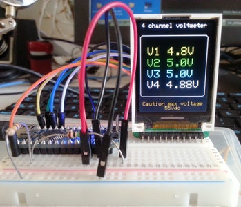
/*--------------------------------------------------------------
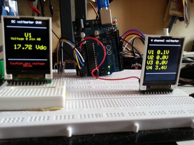
Program: 4 channel voltmeter voltmeter
Description: 4 channel DC voltmeter with voltages displayed
on Color TFT LCD to 1 decimal place, using sampling and averaging
Hardware: Arduino NANO or UNO with voltage dividers on A0 to A3.
TFT LCD connected
Software: Developed using Arduino 1.0.3 software
Date: 10 March 2014
Author:
--------------------------------------------------------------*/
#define sclk 13
#define mosi 11
#define cs 10
#define dc 9
#define rst 8 // reset
#include // Core graphics library
#include // Hardware-specific library
#include
Adafruit_ST7735 tft = Adafruit_ST7735(cs, dc, rst);
// number of analog samples to take per reading, per channel
#define NSAMP 100 // number of samples to take befor displaying
// voltage divider calibration values
#define Dv1 11.00
#define Dv2 11.001
#define Dv3 11.00
#define Dv4 10.985
// ADC reference voltage / calibration value
#define VREF 5.00
int sum[4] = {0}; // sums of samples taken
unsigned char Scount = 0; // current sample number
float AVvolts[4] = {0.0}; // calculated voltages
char cnt1 = 0; // used in 'for' loops
void setup()
{
tft.initR(INITR_BLACKTAB); // initialize a ST7735S chip, black tab
tft.fillScreen(ST7735_BLACK); // clear screen
tft.setTextColor(ST7735_WHITE);
tft.drawRoundRect(2, 20, 120, 110, 5,ST7735_WHITE);
tft.setTextSize(1);
tft.setCursor(5,0);
tft.println("4 channel voltmeter");
tft.setTextColor(0XFF00);
tft.setCursor(0,140);
tft.println(" Caution max voltage 55vdc");
}
void loop()
{
// take a number of analog samples and add them up
while (Scount < NSAMP) {
// sample each channel A0 to A3
for (cnt1 = 0; cnt1 < 4; cnt1++) {
sum[cnt1] += analogRead(A0 + cnt1);
}
Scount++;
delay(10);
}
// calculate the voltage for each channel
for (cnt1 = 0; cnt1 < 4; cnt1++) {
AVvolts[cnt1] = ((float)sum[cnt1] / (float)NSAMP * VREF) / 1024.0;
}
// display voltages on TFT LCC Display
// voltage 1 - V1(pin A0
tft.setTextColor(ST7735_YELLOW,ST7735_BLACK); // set color for V1
tft.setTextSize(2);
tft.setCursor(15, 40);
tft.print("V1 ");
tft.print(AVvolts[0] * Dv1, 1);
tft.print("V ");
// voltage 2 - V2(pin A1)
tft.setTextColor(ST7735_GREEN,ST7735_BLACK);// set color for V2
tft.setCursor(15, 60);
tft.print("V2 ");
tft.print(AVvolts[1] * Dv2, 1);
tft.print("V ");
// voltge 3 - V3(pin A2)
tft.setTextColor(ST7735_CYAN,ST7735_BLACK);// set color for V3
tft.setCursor(15, 80);
tft.print("V3 ");
tft.print(AVvolts[2] * Dv3, 1);
tft.print("V ");
// voltage 4 - V4(pin A3)
tft.setTextColor(ST7735_WHITE,ST7735_BLACK);// set color for V4
tft.setCursor(15, 100);
tft.print("V4 ");
tft.print(AVvolts[3] * Dv4, 2);
tft.print("V ");
tft.drawRoundRect(2, 20, 120, 110, 5,ST7735_WHITE);
// reset count and sums
Scount = 0;
for (cnt1 = 0; cnt1 < 4; cnt1++) {
sum[cnt1] = 0;
}
}
Step 8: Video of Programmable DVM

Participated in the
Full Spectrum Laser Contest

Participated in the
Arduino Contest

Participated in the
Portable Workstations Contest


