

Introduction: Arduino Rolling Ball Kitchen Timer


I have always been facinated by rolling ball clocks and when I saw JBV Creatives "Rolling Ball Escapement" demo I just had to build it into a working project.
This is a general purpose kitchen timer and uses a 3D printed Rolling Ball Escapement from JBV Creative.
The original Rolling Ball Escapement was driven by a weight and string pulling on a ratchet gear.
I have replaced the weight with a stepper motor controlled by an Arduino NANO.
Time remaining is displayed on a 8 digit 7 segment LED display along with other functions.
The timer sound is provided by a JQ9500 sound module that can play any MP3 sound files as the timer alert.
Designed to be wall mounted but can be used on a counter top if attached to a heavey base for example a granite sample as in the animation.
Note extra build information can be found on my site http://www.brettoliver.org.uk/Rolling_Ball_Timer/Rolling_Ball_Timer.htm
Supplies

3D Printed Parts
The image shows the list of 3D printed parts.
The items in red are included with the Rolling Ball Escapement kit.
Note some parts are listed as 0 in the "New Qty" colume as they are not required.
The parts in light grey are included in the zip file.
Parts list
1 off Arduino Nano
1 off Verboard 51 holes x 30holes 31 strips
1 off 28-BYJ48 Stepper Motor and ULN2003 Stepper Motor Driver
1 off JQ6500 sound module
1 off Mottram Labs 0.56" MAX2719 7 Segment Display Module Green
1 off ND Gel Filter Sheet 30mm x 120mm
2 off MP1584EN ultra Small DC-DC 3A power Step-Down Adjustable Module Buck Converter
1 off Wooden Back board 265mm x 110mm (engineered wood flooring off cut)
1 off Bearing 624ZZ
R2 Resistor 3K3
R3 Resistor 3.3K
R1 Resistor 3K
D1 1N4001
R4 100
C3 Electrolytic 220 µF
C2 ceramic 100nF
C1 ceramic 2,5mm, 100nF
F1 Fuse with holder, 1A
1 off 12mm Latching Push Button Switch SPST
2 off 12mm Non Latching Push Button Switch SPST
5 off 6×6×8mm Momentary Tactile Tact Push Button Switch with Button Caps
Various Pin Headers Male & Female
Hardware
Assorted pack M2, M3 & M4 nuts, bolts and washers
6 off Screw caps 14mm
Tools
3D printer
2mm tap for threading the stepper motor
Step 1: General Information

The original escapement above is powered by a weight and is a nice demo of a rolling ball movement and can be purchased here at JBV Creative.
I decided to give the escapement a practical purpose and build a timer using this escapement controlled by an Arduino NANO.
I have removed the weight driven part of the escapement and replaced it with a 28-BYJ48 Stepper Motor and ULN2003 stepper motor driver.
The two "Triggers" that lock the "Ball Track" in place until released by the ball bearing are modified so they no longer lock the "Ball Track".
This allows the tilting of the "Ball Track" to be controlled by the stepper motor only.
By using a combination of speed and acceleration of the stepper motor I was able to get a 5 second ball bearing travel across the ball track.
Designed as a general kitchen timer but used mainly for timing tea brewing the timer has 7 presets based around tea.
These presets are easily changed in code.
The timer can also be set in 10 second increments for any time up to 59 minutes and 50 seconds.
Features
Timer can be set in 10 second increments unto 59 minutes and 50 seconds.
There are presets for 3mins, 3mins 30secs, 4mins, 4mins 30secs, 5mins, 5mins 30secs and 6 mins.
The timer defaults to 4mins 30secs.
Any mp3 file can be set to play one the timer completes.
A number of tracks can be preloaded as timer alert sounds.
Alert sound volume can be adjusted.
A visual alert remains on when the timer alert completes.
Time set and time countdown are shown on 6 digits of a 8 digit 7 segment display.
Step 2: MAX2719 7 Segment 8 Digit Display Module

Thw MAX2719 7 Segment 8 Digit Display Module shows the timer value in the 1st 5 digits and general settings in digits 7 & 8. Digit 6 is always blank.
I have used a Mottram Labs 0.56" MAX2719 7 Segment Display Module.
These are available from ebay for around £5.00
Here is the manufacturers site https://www.mottramlabs.com/
These modules come ready assembled with a surface mount MAX2719 chip.
If you use any other module then you will need to modify the 3D parts 7segmentholder and 7segmentholderRear.
I have included all the FreeCAD files so modifications can be made.
Step 3: Increasing the Contrast on the 7 Segment Modules


The 7 segment displays traditionally would have a sheet of green perspex to match the LED colour placed over the top of the display.
This was designed to hide the not lit segments and provide contrast to the LED segments that are on.
I have used Neutral Density Heat Proof Dimming Transparent Acetate Sheet ND 0.9 but a dark grey would be fine.
This hides the not lit LED segments and provides the contrast needed in bright conditions. It has the advantage that it work on all colour LEDs.
The acetate sheet is also very cheap the only disadvantage is that it is too flimsy to cover large areas without support.
Picture 1 shows the effect of the ND sheet. The lit LED segments have more contrast and the unlit LED segments are hidden. It also hides the black tape masking for the colon display.
Without the sheet the unlit segments are visible and the lit segments are washed out.
Picture 2 Rear of the 7 segment display holder with no ND sheet in place
Picture 3 7 segment display holder with thin strip of ND sheet is added.
Step 4: Modification of the 7 Segment Display Module to Show Colon Digit Separators

- The standard display only has decimal points to separate the digits and has no colon that would normally be used in a clock display.
- In the code I have set digit 5 to always display a "o" lower case o and digit 2 is always blank.
- Black plastic tape is then cut with a craft knife and placed over the "0" digit leaving a small section showing.
- When the display is on these visible sections now display a colon.
- Modified display in position in the 7 segment display holder.
Step 5: JQ6500 Sound Module


The JQ6500 provides the timer output sound and storage for MP3 files.
JQ6500 MP3 Voice sound module can play stereo MP3 files or standard mono audio files.
The module has two different modes to operate in; serial communication mode (connecting to a microcontroller) or AD button control mode (module can be controlled with switches).
This project uses AD button control only.
The timer alert files are in mp3 format and have to be uploaded to the JQ6500 from your PC.
This is a bit clunky as the original uploader was in Chinese only. To make file uploading easier Nikolai Radke has created an English version of the Music tool.
I have put detailed instructions on my web site for this project here.
Step 6: Timer Controls

Button Functions
POWER- Turns power to timer On and Off
START- single press starts the timer
SELECT- Function selector - turning the knob changes the function. the function number selected is indicated on the 7 segment display digits 0&1
Function 1- Timer
Function 2 - Set Minutes 10s (decimal point lights on mins tens digit to indicate changes will be made to this digit).
Pressing "Up" increases the digit to a max of 5.
Pressing "Dn" decreases the digit to a min of 0.
To set the new selected value press the "SET" button.
Function 3 - Set Minutes 1s (decimal point lights on mins unit digit to indicate changes will be made to this digit).
Pressing "Up" increases the digit to a max of 9.
Pressing "Dn" decreases the digit to a min of 0.
To set the new selected value press the "SET" button.
Function 4 - Set Seconds 10s (decimal point lights on Seconds 10s digit to indicate changes will be made to this digit).
Pressing "Up" increases the digit to a max of 5.
Pressing "Dn" decreases the digit to a min of 0.
To set the new selected value and set the new timer value press the "SET" button.
Function 5 - Timer preset 3 minutes. Presss the "SET" button to set the preset to the timer.
Function 6 - Timer preset 3 minutes 30 seconds. Presss the "SET" button to set the preset to the timer.
Function 7 - Timer preset 4 minutes. Presss the "SET" button to set the preset to the timer.
Function 8 - Timer preset 5 minutes. Presss the "SET" button to set the preset to the timer.
Function 9 - Timer preset 5 minutes 30 seconds. Presss the "SET" button to set the preset to the timer.
Function 10 - Timer preset 6 minutes. Presss the "SET" button to set the preset to the timer.
SET- The "SET" button function depends on what function is selected and what the timer is doing at the time.
Cancel Timer- If the timer is running pressing the "SET" button will cancel the timer.
Restore display- If the timer is not running and the display intensity is being changed by pressing the "Up" or "Dn" buttons pressing "SET" will restore the Select display to function display mode.
When setting a custom timer digit or setting a preset timer pressing "SET" sets that time or digit into the timer.
When the timer has completed and the display will show 00:00 and the timer complete LED will flash press the "SET" button to turn the PED off and return to the last stored timer.
Up- Increases the display intensity or increases the selected digit depending on function selected by the "SELECT" control.
Dn- decreases the display intensity or decreases the selected digit depending on function selected by the "SELECT" control.
JQ6500 Module Controls
Play - Plays the currently selected track file.
Vol+ - Short press next track and long press Volume up.
Vol- - Short press previous track and long press Volume dpwn.
Step 7: Veroboard Layouts


There are 2 Vero Board layouts, the main board and the switch board.
The switch board wiring and resistors (not the switches) are all on the copper side of the board.
Pic1. Boards with modules in place.
Pic2. Boards with modules removed to show wiring.
Pic3. Rear of boards- note resistors and wiring on the rear of the switch board.
Full size layouts are available from my website if required.
Step 8: Veroboard and ULN2003 Board Locations on Mounting Board


The 2 images show the loacations of the spacers, main veroboard and the ULN2003 Board on the mountig board.
Note the 2nd Verboard is mounted on the rear of the "switch_mount" 3D printed part.
Step 9: Schematic
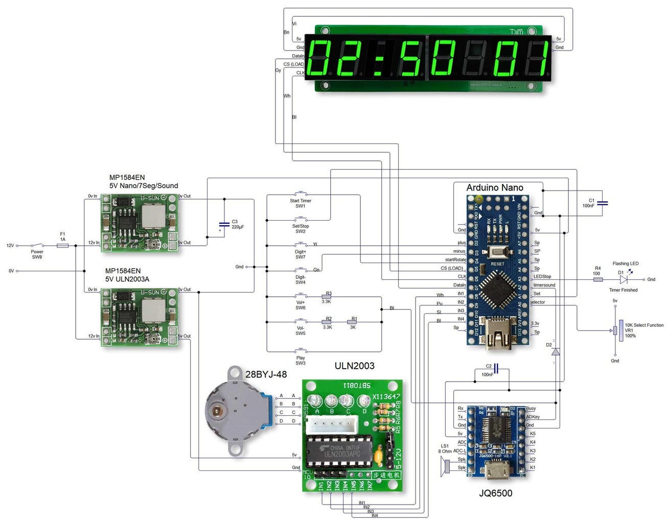
Note The JQ6500 specifies an 8Ω 3w speaker.
A full size image of the schematic is available on my website if required.
Step 10: 3D Printed Parts Locations


The 3 images show the locations of the 3D printed parts I have designed for this project.
For further details on each 3D printed part refer to my website here.
For the "Rolling Ball Escapement" follow the instructions with the kit.
Step 11: Spool Gear Modification


To work with the stepper motor the "spool gear" supplied with the "Rolling Ball Escapement" kit will need to be modified.
Pic1. The original spool gear from the rear.
Pic2. My "servo_drive" 3D part is glued to the back keeping the holes aligned.
Pic3. Original spool gear front view.
Pic4. The end pin is cut off level with ratchet gear housing.
Pic5. My 3D part "spoolgearcover" is clipped over the top.
Step 12: 28BYJ48 Stepper Motor Modification

To fix the 28BYJ48 Stepper Motor to the "spool gear" supplied with the "Rolling Ball Escapement" kit the stepper motor will need to be modified by adding a tapped hole in the spindle for a M2 bolt.
The 28BYJ48 Stepper Motor spindle is quite soft and can be drilled easily. I drilled a 1.8mm hole using the center mark on the spindle as a guide. I then added a M2 thread using a tap. Tap kits are available from Amazon if you don't have one already.
Step 13: Mounting the Modified Spool Gear & Stepper Motor


Mounting The Modified Spool Gear & Stepper Motor onto the "Base" supplied with the "Rolling Ball Escapement" kit.
Pic1. Mount the stepper motor centrally in the original bearing by drilling 2 off M2.5mm holes and fix with 2 off M2 nuts, 2 off M2 bolts and 4 off M2 washers.
Pic2. The modified "Spool Gear" is then connected to the threaded stepper motor spindle with a M2 bolt.
Step 14: Mounting Switches & Switch Panels

Mounting Switches & Switch Panels onto the "Base" supplied with the "Rolling Ball Escapement" kit.
See Pic1. for details.
The Power button requires a 12mm hole drilled in the frame of the base.
The control_mount requires 2 off M2.5mm holes for the M2 fixing bolts,nuts and washer.
The switch_mount needs 2 of M2.5mm holes drilled in the base for the mounting bolts.
The mountain bolts fit through the switch Veroboard as well as the switch mount to hold them all in place.
Step 15: Trigger Modification

The original trigger locks the Ball Track in place until it is release by the ball bearing at the end of it's travel.
As the Ball Track tilt is now controlled by the stepper motor the trigger mechanism is not actually required.
I have decided to keep the triggers as they add to the illusion that the clock is ball bearing controlled and also adds "movement" to the clock.
To prevent the triggers from locking the ball track the locking step will need to be filed off so there is a smooth transition up the trigger shafts.
See Pic1. for details.
Step 16: Mounting the Timer


The timer is mounted on a 260mm x 110mm engineered Oak backboard (an offcut from my laminate floor) with a black vinyl iron on edge.
My timer is wall mounted but a heavy base like granite could be used as an alternative for worktop mounting.
The locations for the wall anchors are marked out using the Mounting Guide supplied with the JBV Creative download.
Pic1. The first holes are 60mm down from the top of the board.
Pic2. The lower set for my 7 segment display use the same guide.
Pic3. Holes ready for drilling out. I used M4 bolts and nuts but wood screws would be quicker.
Pic4. The "wall anchors" supplied with the "Rolling Ball Escapement" kit are screwed or bolted in place.
Pic5. The "wall post " supplied with the "Rolling Ball Escapement" kit are then screwed into the anchors.
Note the lower pair of wall posts are drilled to take a 3mm bolt to take the extra weight of the 7 segment display.
This will need a 2.5mm hole so the 3mm bolt will "self tap" into the hole.
Step 17: Panel Labelling


Panel labels are made from Inkjet transfer paper.
Individual labels are cutout, applied then varnished over in clear matt.
Just follow the instructions that come with the Inkjet transfer paper as it will vary by manufacturer.
I have included my label sheet in PDF format. The sheet includes a scale measure to check the finished print is the correct size.
Attachments

Step 18: Finishing Touches

I covered any exposed pivots with 14mm metal screw caps I had laying around in my workshop.
I used the metal cap part only and glued or screwed them in place.
Step 19: Setting Up the Timer

The timer needs setting before first use and subsequently if the timer is stopped in mid cycle.
The timer is set by turning the Spool Gear cog by hand until the Ball track is all the way over to the left at it's lowest point.
This can be easily confirmed by checking the Link bar is directly over the M4 nut on the Link Gear cog.
Step 20: Code & 3D Printed Parts Download
My 3D printed parts including FreeCAD files can be downloaded from my website.
The 3D printed parts for the "Rolling Ball Escapement" have to be purchased as a kit from JBVCREATIVE.


