

Introduction: Sherman Tank Clock


3D Printed Memorial Clock for my Gt. Uncle Trooper Cyril Arthur Brindley & the men of the 24th Lancers who died while serving their country in WW2.
The tank clock uses two stepper motors, one to drive the tank body on a turntable to display the hours and the other to drive the clock turret to display the minutes.
The clock is controllrd by a ESP32 WROOM 32D Microprocessor and has a JQ6500 sound module to play the clock chimes.
Designed around a 1:35 scale M4 Sherman Tank this clock should work on any similar sized tank with a central turret.
See my website for this clock here http://www.brettoliver.org.uk/Sherman_Tank_Clock/sherman_tank_clock.htm
Supplies

List show electronic componants required. LEDs show 5 RED but see schematic for actual colours.
You will also need the following electronic modules.
1 off ESP32 WROOM32D
2 off Nema 17 Stepper Motor Bipolar (17HS4023) 1.8 Degree 4.1V 1A 13Ncm
2 off TMC 2209 Stepper Driver
2 off 3144E Hall effect sensor
2 off magnets
1 off JQ6500 sound module
1 off LM 2596S Requlator Module
Veroboard 33 strips v 42 holes
Optional
LED controller and LED strip
Step 1: Features & Functions
- 3D printed case on an Oak base with a Perspex display dome.
- The large 300mm case is designed to be printed on a 230mm x 230mm printer bed.
- Displays the time using a 1:35 scale Sherman Tank model. The tank body displays the hours and the turrent the minutes.
- Time is auto set from the internet via the ESP32 WROOM32D micropocessor.
- The clock has full quarter chimming and hours as well as a 2min silence completion chime for 11:00am every 11th November.
- Chimes can be set to 24/7, daytime only or off and the volumn can be adjusted.
- Daylight saving time is controlled by a single switch.
Step 2: Telling the Time

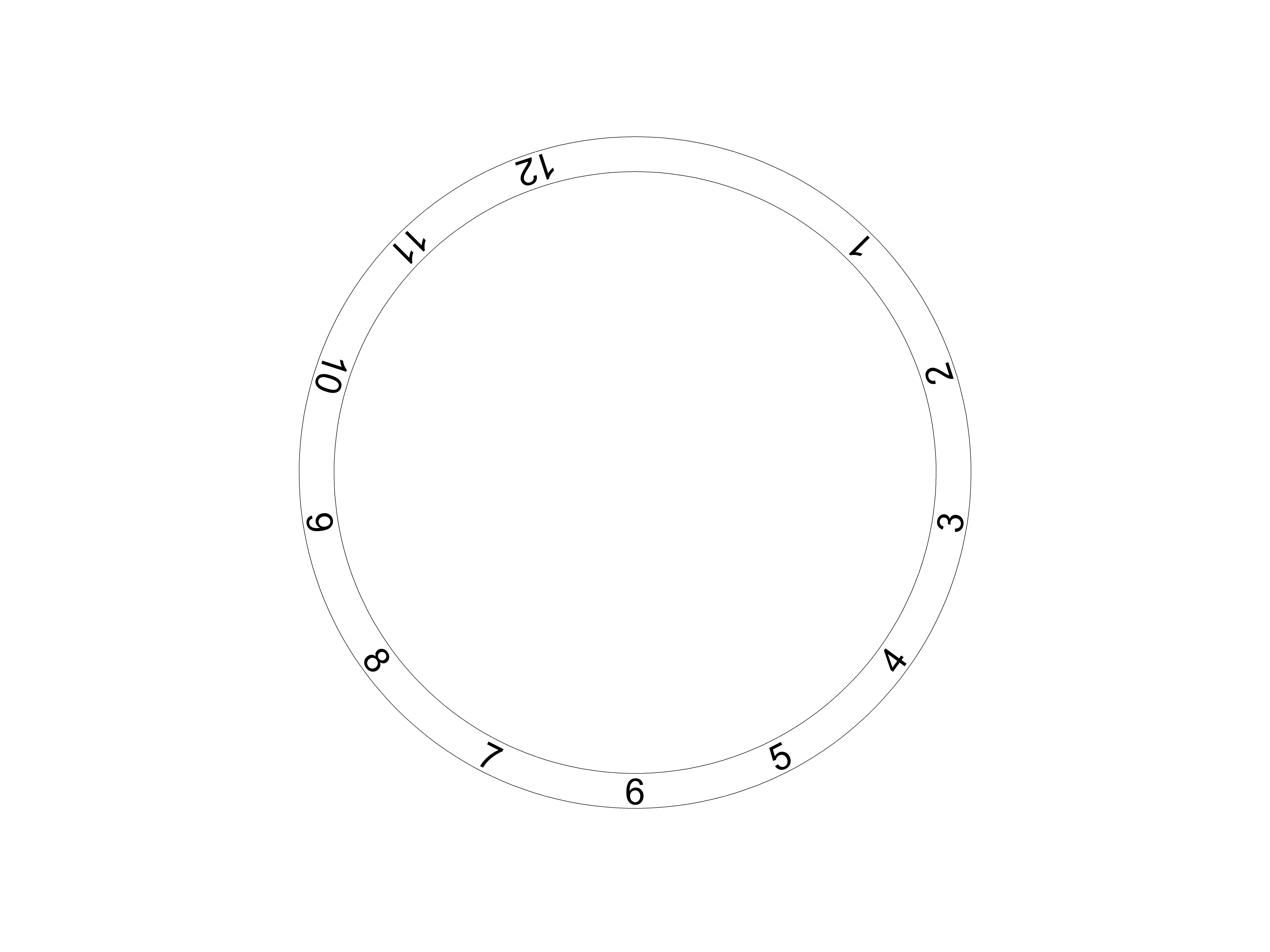
The hours are simply read off the hour ring as it passes the 24th Lancers badge. The hour ring revolves with the tank body and increments once an hour.
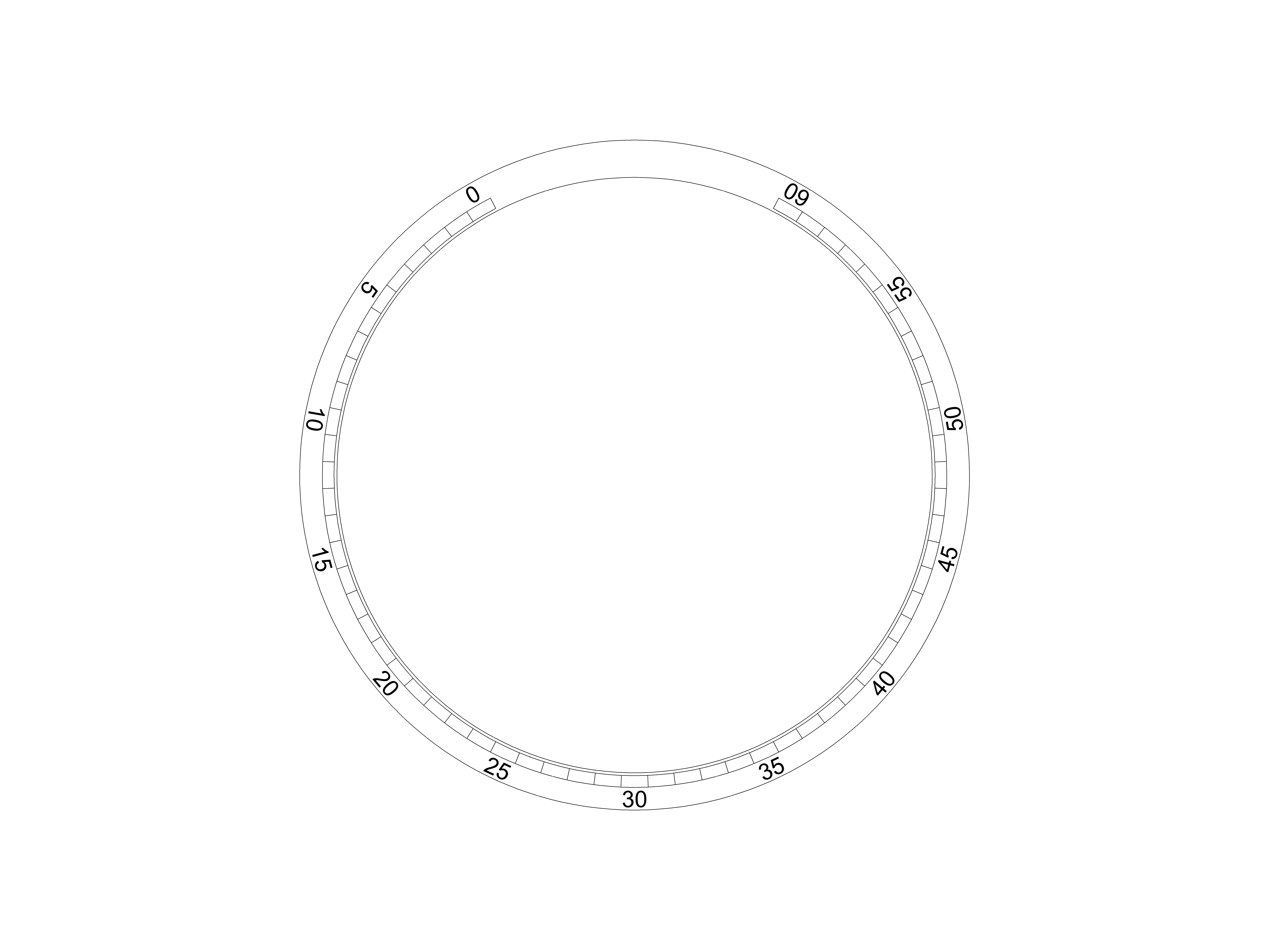
The minutes are read off the tank turret/gun barrel. The turret increments once a minute.
The time indicated below is 1:04.
Step 3: Model Sherman Tank


The clock uses a 1:35 scale Early Production Sherman Tank Model from Tamiya.
There are many Sherman Tank versions and after studying actual WW2 images and videos of the 24th Lancers at that time I chose this model as it contained various Sherman Tank versions in the kit.
I have attempted to base it on a 24th Lancer C Squadron Tank as my Gt Uncle Cyril Brindley was in C Squadron.
British tanks were given names by the crews based on the company they belonged to. A company tanks would be given names starting with A, B company starting with B etc. My Gt Uncle was in C company so his tank would have started with C. I was not able to find the name of his Tank so have named it "Cyril Brindley" after him.
There are many Sherman Tank kits on the market so you can add the Sherman Tank varient or any other similar sized tank of your choice.
I have painted and decorated my tank from the Normandy era. You can add paint effects of your choice. There are many YouTube videos detailing painting effects for model kits. You also find plenty of online guides to show what lables were on each tank.
Step 4: Operating the Clock

Setup
Before use set the following in code.
timezone line 117
Wifi SSID line 127
Wifi password line 128
The clock is very simple to use with minimum intervention from the user.
On power up the clock will aquire time from the internet.
Once the time has been obtained the clock will auto set to the home positions- 1 hour and 0 seconds.
On pressing "Start Clock" the clock turns the tank body and turret to indicate the exact time.
Time is now updated every 1 minute indicated by the turret with the tank body moving every hour to indicate the hours.
Chimes are set as required on 24/7, daytime only or off.
In summer the "DST On" button is pressed followed by the "Start Clock" button to advance the clock by an hour.
In winter the "DST On" button is released followed by pressing "Start Clock" to retard the clock 1 hour.
Step 5: Clock Controls & Indicators

The control panel has 8 switches 3 locking and 5 non locking as well as 5 panel mount LEDs.
Switches Latching
Chime On - When on chimes are enabled.
Chime 24/7- when on and Chime On is also on allows the chimes to sound 24/7.
Chime 24/7- when off and Chime On is also on allows the chimes to sound only during the preset times in the Arduino code.
DST On- When activated the clock will show DST (summer timw) & when off the clock will dsiplay winter time.
Note press "Start Clock" to set the clock to the new time.
Switches Non- Latching
Chime Vol + Increases the chime volume to max of 30.
Chime Vol - decreases the chime volume down to 0.
Start Clock after power on and the clock has stopped at the home location 1h 0m pressing this button sets the clock to the correct time.
Reset Clock Pressing this button resets the clock.
Step Hour this button rotates the hour hand by 1 hour and is used for setting up the clock.
LED Indicators
End Stop Hours this LED lights when the Hour endstop sensor is activated.
Note End Stop Hours LED will flash(and the clock is stopped) if the end stop is not reached in a preset number of steps.
WIFI Seach This LED flashes while the clock searches and logs into a WIFI Network.
WIFI OK This LED illuminates when WIFI is succesfully logged in.
WIFI FAIL This LED illuminates while there is no succesful WIFI login,
End Stop Minutes this LED lights when the Minute endstop sensor is activated.
Note End Stop Minutes LED will flash(and the clock is stopped) if the end stop is not reached in a preset number of steps.
Step 6: Control Panel LED Indicators

On Power on the WIFI fail indicator lights to show WIFI is not connected.
The WIFI Search Indicator will now flash as the clock finds and gets the time from the NTP set in code.
Once NTP time is obtained the WIFI OK indicator lights to confirm.
After a short delay the tank body rotates to it's home position at 1hr.
When this position is reached the End Stop Hour indicator illuminates to indicate hour home is reached.
Once End Stop Hour is reached the tank turret starts to rotate to the End Stop Minutes position (o mins).
The End Stop Minutes indicator lights when the tank turret points to 0 minutes .
The clock now stops and waits for the Start Clock button to be pressed.
Step 7: Home Failure Indicators


End Stop Fail
If the clock at any time fails to find the hour or minutes end stop the tank body or turret could spin forever.
The clock detects if too many rotations have taken place it will stop the clock and flash the End Stop Hour or End Stop Minutes indicators.
Animation 1 End Stop Hour not found
Animation 2 End Stop Min not found
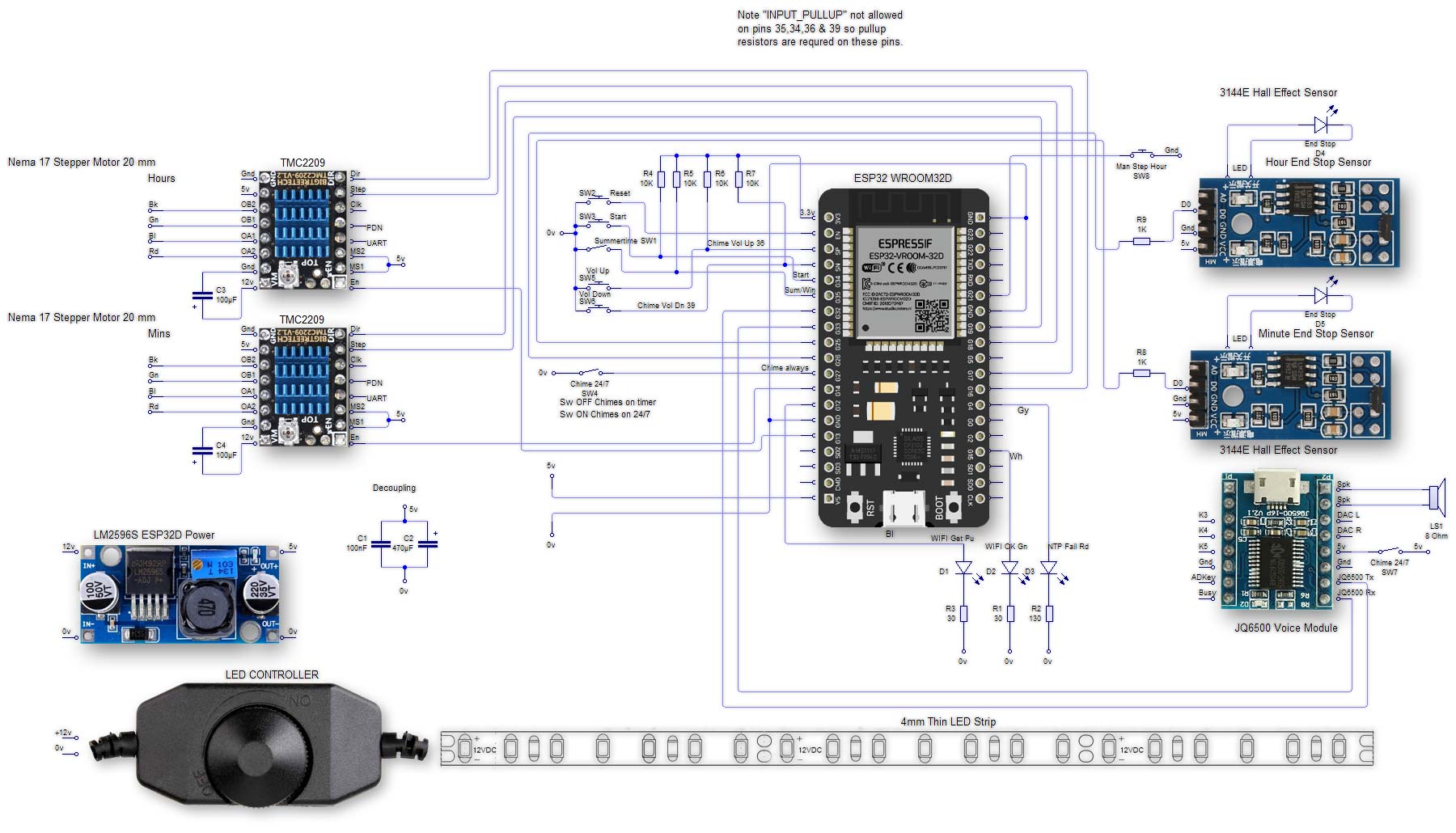
Step 8: Schematic

Full size schematic can be found here.
Schematic shoes optional LED strip.
Step 9: Veroboards


Veroboard layouts. Note the fuse board is cut off from the main board and mounted seperatly.
Step 10: Cap Badge Hour Pointer


Pic.1 A replica silver cap badge was purchased from Ebay.
This is the 24th Lancers Cap badge but any cap badge replica can be found online.
I painted the badge matt black then rubbed the high areas back to give an aged effect to the badge.
Pic.2 The badge was then painted and then glued to the 3D printed badge mount.
Pic.3 The completed badge on it's case mount. The top centre of the badge indicates the hours
Step 11: 3D Printed Parts


Apart from the Oak base the clock is built up from 3D printed parts that can be downloaded at the end of this Instructable.
A complete list of parts and detailed descritions can be found here.
All the 3D parts are my own design apart from the clock turntable and drive gear which were downloaded from https://www.printables.com/model/127726
The instructable is here https://www.instructables.com/3D-Printable-Timelapse3D-Scanning-Turntable/?utm_source=YT
Many parts of this large 300mm (1ft) diameter clock were too big to be printed on my Ender 5 Pro so have been designed in smaller parts that are bolted together. Examples are shown in pic.1 base and pic.2 dial bezel.
Step 12: Mounting the Tank in the Clock


Pic.1 shows the Clock with spindle connector attached to the minute stepper spindle.
If use a M2 bolt in the lower hole to fix in place.
Pic.2 A large hole is drilled in the base of the tank hull so the spindle connector can pass through.
Pic.3 Remove the engine hatch from the model to access the spindle connector.
Pic.4 With the turret removed place the tank body onto the turntable and position it as required.
I position it so the front of the tank is between 1o'clock and 12'oclock.
Pic.5 Replace the turret on the tank so the spigot on the turret fits into the spindle connector and tighten the M2 bolt on the spidle connctor to lock it in place.
With the clock powered on wait until the turret stops turning and the "End Stop Min" indicator is lit.
Pic.6 Losen the M2 bolt so the turret is free to rotate without moving the stepper motor.
Move the turret to the 0 minute position and tighten the bolt.
Reset the clock and check the turret points to the 0 minute when the endstop is reached.
Replace the engine hatch and press the "Start Clock" button and the clock will now tell the time.
Step 13: Constructing the Wooden Base


Pic.1 Place the completed base and control panel on your chosen piece of timber.
Pic.2/3 Draw around the base leaving whatever overlap is required.
Pic.4 Cut out the base with a jigsaw.
Clean up the cut edges.
Pic.5 Using a router add a bevelled edge
Pic.6 Paint or varnish the timber base as required then fix all the clock parts to the base.
Pic.7 Stepper Motors & Turntable in place
Pic.8 Tank in place
Step 14: LED Strip Illumination


The optional 12v LED strip gives some illumination to the clock is controlled by a LED controller pic.3.
The control board pic.2 is removed from the case of the led dimmer and the variable resistor on the reverse side is mounted on the clock case by drilling a suitable sized hole pic.1.
The 12v input connector is left in place and the output is removed and connected to 12v.
The output is wired to the LED strip on top of the base.
The plug and socket on the 12v feed and input allow the base to be removed for maintenance.
The LED control board is fixed to the case via the variable resistor mount.
Step 15: Turntable and Clock Construction 1


Pic.1 The steppers motors, electronics and 3D parts of the clock internals.
Pic.2 All the parts are built off the 3D printed "base11" shown below flipped upside down.
Pic.3 Bottom view of Base11
Step 16: Turntable and Clock Construction 2


Pic. 1 Mount the 3 off "bearingmountcenter" on the three legs as shown below.
Loosely fix in position with 6 off M3 Bolts, 12 off M3 Washers and 6 off Nyloc nuts.
Pic.2/3 Glue center 22mm x 7mm x 7mm bearing in place flush with the rear of the round plate not the square stepper motor plate so it sits out from the other side of the plate a few mm.
Note the bearing is fitted flush to base not the sqaure stepper mount.
Pic.4 Insert the 3 black printer bearings onto the 3 "bearingmountcenter" and secure with M2 self tappers and M2 washers.
Step 17: Turntable & Clock Construction 3


Pic.1 Fix the "Bearingmounthour" loosely in place to the "base11" with 4 off M3 bolts, nyloc nuts and 8 washers.
Once the geared turntable in in place the hour stepper motor is adjusted so it meshes correctly with the turntable gears.
The 3D printed part "Hi-Gear-56-Teeth" is pushed onto the hour stepper shaft below the bracket once the hour stepper has been mounted.
Pic.2/3 Mount the hour stepper motor on top of the "Bearingmounthour" and fit the "Hi-Gear-56-Teeth" onto the motor spindle.
Pic.3 Mount the minutes stepper motor in place in the center of the clock.
Oic.4 Glue a neodymium manget wih super glue to the "MagnetMountMins" then super glue the "MagnetMountMins" to the rear shaft of the minute stepper.
Step 18: Turntable & Clock Construction 4


Pic.1 Fit the hall sensors to the "HallSensorMountHour" and "HallSensorMountMin" brackets with M2 Nyloc nuts, bolts and washer.
Fit the "HallSensorMountMin" bracket in place with M2 self tappers close to the minute sensor magnet so the hall sensor is triggered when the "MagnetMountMins" attached to the stepper shaft rotates.
Note there are no holes printed fo the backets so mark and pre-drill holes as required.
There is a bit of adjustment built into both brackets.
Pic.2 The "MagnetMountMins" attachemennt to the stepper shaft is very fragile so I have designed a protective cover that just slots over the rear of the minute stepper.
"HallSensorCoverMins" in place over the minutes stepper motor and sensor mount.
Pic.3 The Vero Boards, and modules are mounted on 5mm 3D printed "verspacers".
The spacers accept 2mm self tappers and holes for these will need to be drilled as required.
Pic.4 Vero Boards and modules fixed in place with self 2mm self tappers.
Step 19: Turntable & Clock Construction 5


Pic.1 Three support/fixing brackets are made up from these parts 1 off "MinuteRingBracket", 1 off "MinuteRingOuterBracket" and 1 off "turntableBracket".
See pic.2 for location and fixing details. Fixings with M3 Bolts, Nyloc nuts and washers. The only exception is the "turntableBracket" is fixed with a single M2 self tapper.
Pic.3 Brackets in place ready to fix to the base/clock surround.
Step 20: Turntable Build 1


Pic.1 The "hourring" below is fitted to the top of the turntable with 6 off 2mm self tappers.
Pic.2 Turntable fixed through the back to the "hourring" with M2 self tappers.
Pic.3 The Geared turntable is fixed to the turntable with self tapping screws. Ensure the geared turntable is fitted in the exact center of the turntable as this is a rotating part.
Note the spigot glued to the middle of the geared turntable.
Pic.4 Picture of complete turntable. Washers under the M2 self tapper are there to prevent the selftappers from showing throught the hour ring.
Depending on the length of M2 self tappers you have available these mat not be required.
Step 21: Turntable Build 2


Pic.1 The main clock body loacted in place inside the geared turntable.
Note the hour gears meshing and the center bearing located over the spigot. This bearing and the three black bearings take the weight of the geared turntable, turntable and tank body.
Pic.2 Completed turntable fitted to the clock movement (from below). This is now ready to mount into the clock surround.
Step 22: Final Clock Build 1


Pic.1 The case is fixed to the wooden base and movement.
The case fits into 4 off "baseouterfixings" which are fixed to the wooden base with 2 off M2 selftappers each.
Pic.2 Mount the clock movement onto the base losely at first.
Pic.3 Case fixing.
Pic.4 Line up the badge with the middle of the control panel and fix the clock case in place.
If you have fitted LED lighting plug the LEDs into the controller before putting the case on.
Step 23: Final Clock Build 2


Pic.1 Top view showing the case in place.
Pic.2 The upper fixings of 3 x M2 self tappers locate into the turntablebrackets as
Pic.3 4 x M2 bolts hold the case to the "baseouterfixings" via drilled holes.
Once the case is fixed in place lower the completed turntable onto the geared turntable ensring that the gears are engaged.
Ensure that there is an even gap all round the turntable then remove the turntable and tighten the screws on the "baseouterfixings".
Pic.4 Replace the turntable.
Step 24: Final Clock Build 3


Pic.1 Fit the "spindle connector in place on the minute bearing spindle and ensure when the spindle turns it stays centered.
Pic.2 Spindle connector in place.
Pic.3,4,5 & 6 Remove the turret and engine cover from the model.
Pic.7 Locate the tank body over the spindle through the hole cut in the tank body floor.
Step 25: Final Clock Build 4


Pic.1 Turn the tank body to half way between 12 and 1 on the hour ring.
Align the turret to 0 on the minutes ring and tighten the lock screw.
Pic.2 Test every thing is fine by reseting the clock and checking the tank turret points to zero minutes and the tank body/hour ring stops at 1 hour.
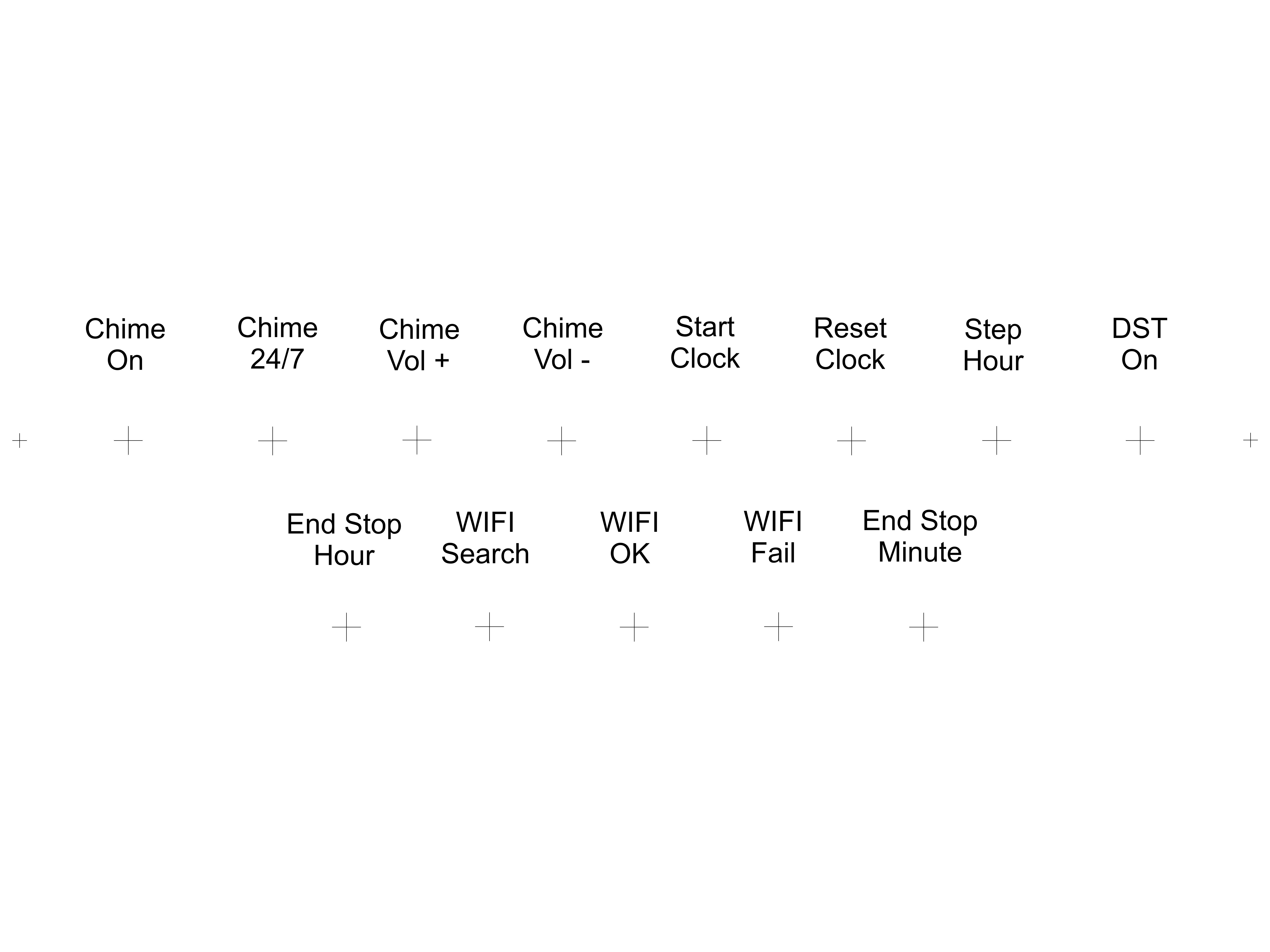
Step 26: Decals


I printed any Decals to be applied to a white background in clear injet transfer paper and decals to be applied to a dark backgound in white inkjet transfer paper.
Pic.1/2 Control Panel Decal download full size file here.
Pic.3 Minute Ring Decal download full size file here.


