

Introduction: Arduino - Sensors and Actuators


Arduino is popular microcontroler. It’s cheap. There’s lots of sensors that can be used with Arduino, as well as actuators.
But exactly what Arduino can be used for?
Well, this is not simple to answer. Or maybe it is: Arduino can be used for controlling whatever you want. Ok, ok! It’s not that much, let me restate: if you respect Arduino memory and cpu limitations, it can be used in small projects to control a lot of things. As “control” I mean monitor some situation, like temperature, umidity, light, and react when a threshold is reached, for example turn on a pump, light, heater, etc.
What you’ll use Arduino for depends on your needs. You may use it to learn robotics, feed your pet, control a simple robot, monitor your house temperatures, or even to help you making kraft beer (https://www.instructables.com/id/Arduino-Homebrew/).
Depending on your needs, you’ll need to use sensors and actuators, you’ll need to use or build (write) some code. As I wrote before, there’re lots of sensors and actuators that can be used with Arduino. Which ones will you use is very specific to your project.
This instructable goal is to present some basic concepts, sensors and actuators. We have a input button, distance and temperature sensors, a potentiometer as an analog input, some leds, a servo, a relay and a lcd display as output or “actuators”.
Code will be explained in parts.
Step 1: Parts Needed
Disclaimer: I use sparkfun links because they're shorter than the other sites I usually buy my arduino stuf.
Please feel free to reuse any component you have and buy from the nearest or easiest store for you.
;-)
- Arduino Mega (you can use a smaller one, just change pins assignments)
- Nokia lcd (https://www.sparkfun.com/products/10168)
- Ultrasound sensor (https://www.sparkfun.com/products/13959)
- White LED (https://www.sparkfun.com/products/11118)
- 3x 330 ohms resistor (https://www.sparkfun.com/products/14490)
- 1x 1K ohm resistor
- DS18b20 temperature probe (https://www.sparkfun.com/products/11050)
- 1-Channel 5V Relay Module for Arduino (https://www.ebay.com/itm/DC-5V-1-Channel-Relay-Module-Optocoupler-Isolation-Control-Board-Dual-Power-/201914359088)
- Colored LEDs: 4 red, 2 yellow and 2 green (https://www.sparkfun.com/products/12062)
- Push button (https://www.sparkfun.com/products/9190)
- Potentiometer (https://www.sparkfun.com/products/9939)
- Servo (https://www.sparkfun.com/products/9065)
Step 2: Some Concepts
What is a sensor?
In simple words, a sensor is a device that “listens” to the physical environment and tells you what happens . Each sensor is able to listen to a specific input, that can be light, heat, motion, moisture, pressure, or any one of a great vairety of other environmental phenomena.
What is a actuator?
In the strict meaning, actuator is a device that converts energy in movement. It could be a valvle or a motor. But I preffer not to be so strict, I consider an actuactor anything that can convert electric energy in an output, for example a display, a led, a loudspeaker.
Digital and Analog
Information may be represented and trasnmitted both in analogic or digital format. The difference between them is that in analogic technology information is represented by amplitude variations, while in digital it’s represented in binary format.
Arduino can do analog and digital inputs, and only digital outputs. The sensors themselves usually are analog, but most of times they have a small circuit that translates values into digital format. In some cases you’ll find both connectors on the same device.
So, analog pins on Arduino are always input. Digital pins can be input or output, your code will tell wich.
Libraries
In programming, library is a piece of code that someone else previously wrote that can help you avoinding reinventing the weel.
Most of, if not all, the peripherals that can be attached to an Arduino have a library. The library controls the hardware, hiding complexity behind some simple routines that someone else wrote and we can use.
Step 3: Start Building Your Toy
Let’s assume that you’ve already been presented to the Arduino IDE and know some about the C language used by arduino.
I have some code organization rules: my code starts with some remarks about the project, I always include libraries at top of the program and then declare all global variables and constants next. I like to use procedures and functions, to make code easier to read and maintain.
Besides these, remember that Arduino code has two mandatory structures: the setup and the loop procedures. The first runs once when the controller is started and the other runs until it’s turned off.
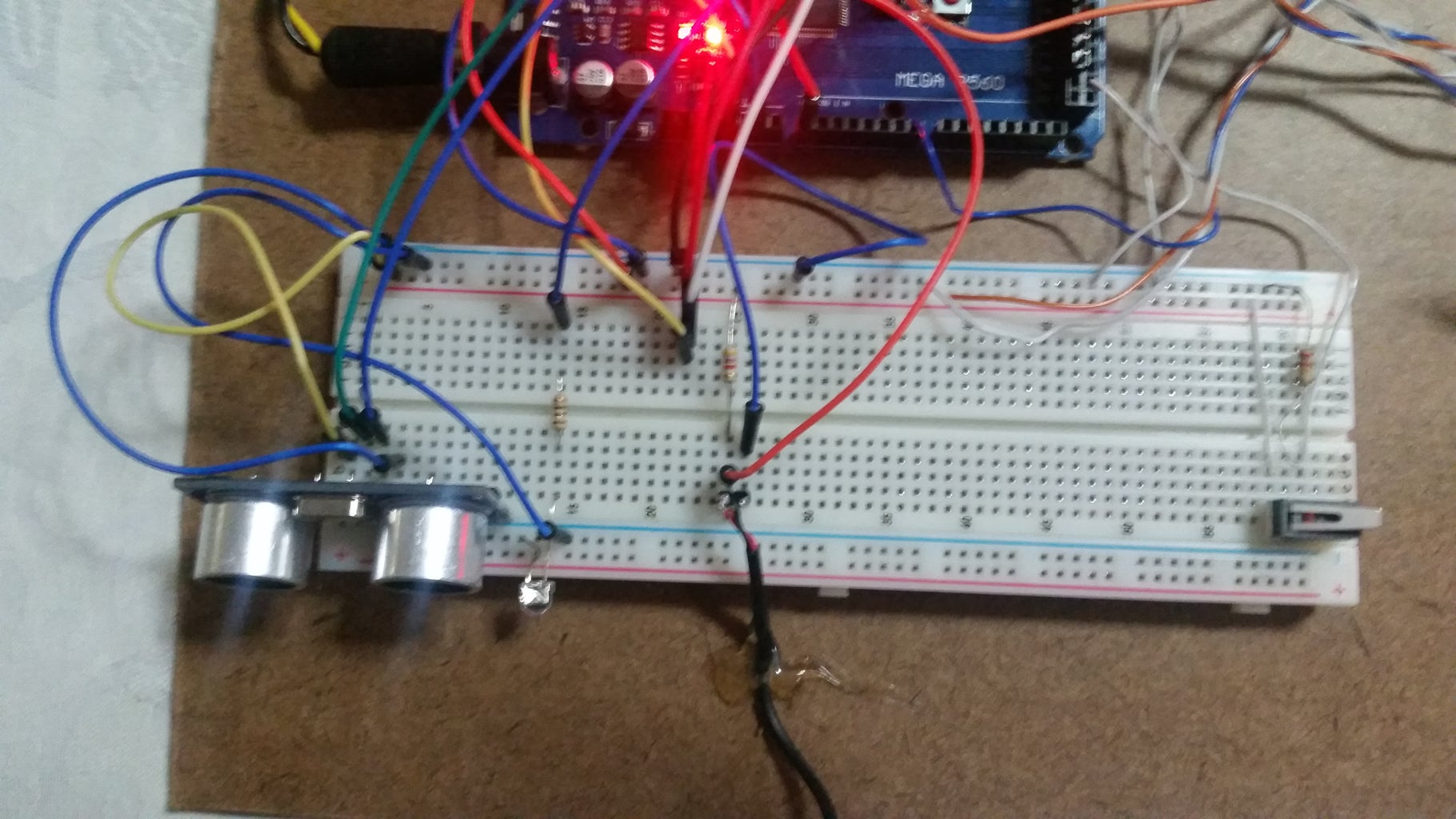
General
Use a small proto board to help making connections.
At first, connect Arduino power pins to the board:
5V to + line
GND to - line
Step 4: LCD Display
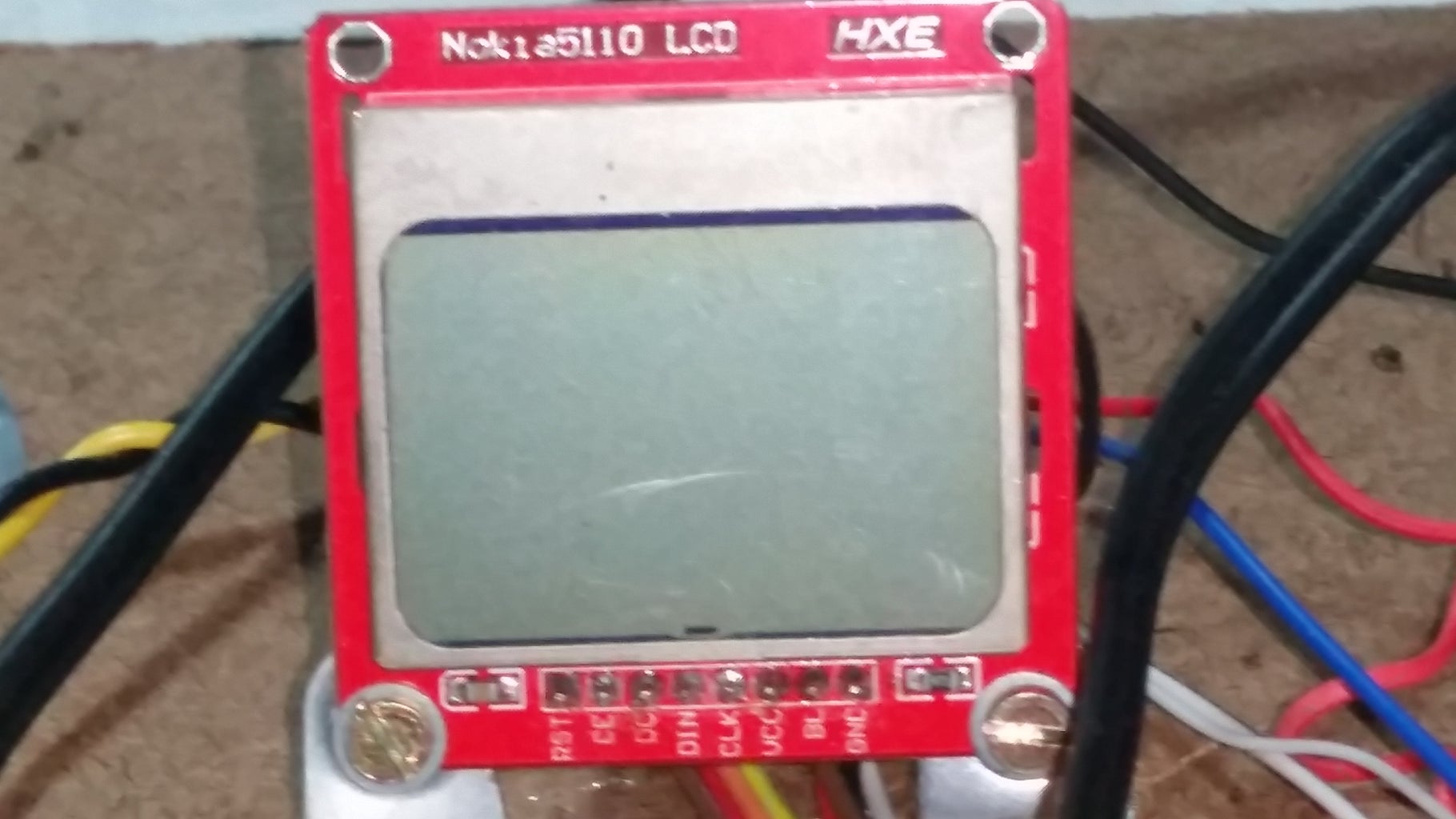
The LCD in this project was used in Nokia cell phones. It’s cheap, may show graphis as well as text in different sizes. If you use other than Adafruit_PCD8544 lybrary, you can chance text and numbers style.
Connect the Nokia LCD to your Arduino mega:
RST to pin 8
SCLK to pin 7
CS to pin 6
D-C to pin 5
DIN to pin 4
To use the Nokia LCD display we’ll use a Adafruit library.
Type at the start of your code:
#include <Adafruit_PCD8544.h<br>
Define the pins used to control the LCD:
// digital PINS definition:
#define lcd_RST  8  // LCD reset (RST)
#define lcd_SCLK 7  // Serial clock out (SCLK)
#define lcd_CS   6  // LCD chip select (CS)
#define lcd_D-C  5  // Data/Command select (D/C)
#define lcd_DIN  4  // Serial data out (DIN)
And create a variable called “Lcd”, using the library sintax:
Adafruit_PCD8544 Lcd = Adafruit_PCD8544(lcd_SCLK, lcd_DIN, lcd_D-C, lcd_CS, lcd_RST);
At first we’ll write something on the LCD just once. Inside the “setup()” procedure paste the code bellow:
Lcd.begin();          // initializes the display
Lcd.setContrast(60);  // sets the display contrast
Lcd.clearDisplay();   // makes sure the display memory is empty
Lcd.setTextSize(1);   // normal size text font
Lcd.setCursor(5,10);  // coordinates are set in pixels, first value is collumn,second is line
Lcd.println("Hello world!");
Lcd.setTextSize(2);   // bigger text font
Lcd.setCursor( 6,16);
Lcd.println(":-)"));
Lcd.display();        // in this display, nothing is shown before you call "display"
This will activate LCD and write some text on it.
In this display using this library, you first put things on the buffer and then tells display to show, so do always call the display() procedure.
Test your code now and see if display works fine. If not, review wire connections and code.
Step 5: Distance Sensor
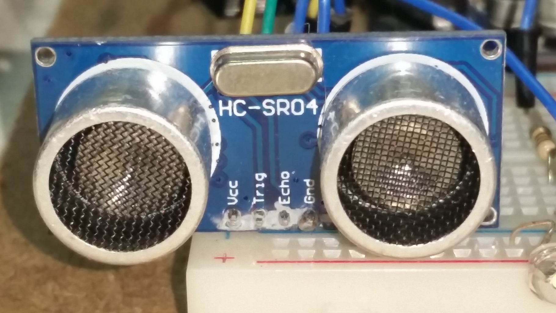
A HC-SR04 ultrasonic ranging sensor is used to measure distances. This sensor is very economical and provides 2cm to 400cm of non-contact measurement functionality with a good ranging accuracy.
The sensor has only four pins: VCC (Power), Trig (Trigger), Echo (Receive), and GND (Ground).
Connect the sensor:
VCC to proto board + line
GND to proto board - line
Trig to Arduino pin 9
Echo to Arduino pin 10
Next to the Adafruit library include, type:
#include <Ultrasonic.h>
Define the pins used to control the LCD:
// digital PINS definition:
#define Ultrasonic_echo     10
#define Ultrasonic_trigger  9
Next to the previous Lcd definition, define Ultrasonic:
Ultrasonic ultrasonic(Ultrasonic_trigger,Ultrasonic_echo);
The ultrasonic sensor has no initial setup, so let’s go to loop section:
Lcd.setTextSize(1);  // makes sure text size is small
Lcd.clearDisplay();  // clears previous display buffer contents
Lcd.setCursor(0,0);  // positions cursor at left upper corner
Distance = ultrasonic.distanceRead(); // reads sensor
Lcd.print (F("Distance "));
if (Distance >= 100) {              // if distance is greater than 100 cm
   Lcd.print(Distance/100);         // shows it in meters
   Lcd.print (F("m"));
}
else {
   Lcd.print(Distance);
   Lcd.print (F("cm"));             // shows it in centimeters
}
Lcd.display();
delay (200);  // a short break to our processor
Test your code now and see if display shows the distance, put your hand in front of sensor to see if it changes. If not, review wire connections and code.
Step 6: Distance Luminous Alarm

Imagine you want something to happen when distance measured by your sensor is too short. It may be a robot avoiding a obstacle, turning on a ceiling light, ringing a bell.
In our project we’ll turn a light on. Arduino ports can drive only a little power, so at this point we’ll turn on a LED. In order to control big loads you’ll need an external driver or power circuit, later on I’ll give an example, see Temperature alarm bellow.
LEDs must (almost) always use resistors to control current, or they won’t last long. For my hight bright white led I used a 330 ohm resistor. You may try different LEDs that will require different values for the resistor. See this instructable: https://www.instructables.com/id/Choosing-The-Res...
LEDs usually have two legs and must be connected properlly:
- the long leg, called anode, goes to the positive wire
- the short leg, called cathode, to the GND.
Connect the LED and the resistor, use the proto board:
LED cathode to the - line
LED anode to one leg of the resistor
the other leg of resistor to Arduino pin 22
No library is necessary now, just define the pin used with the LED:
// digital PINS definition:
#define DistanceLed         22
Set the LED port in the ‘setup’ section:
// pins settings
pinMode(DistanceLed, OUTPUT );
And at the bottom of ‘loop’, type:
if ((Distance > 0) && (Distance < 10)) { // if distance is less than 10 centimeters
   digitalWrite(DistanceLed, HIGH);      // turns light on
}
else {
   digitalWrite(DistanceLed, LOW);       // else turns light off
}
Test your code. If distance is less than 10 centimeters, light should turn on. If it not works, review your wires. You can test the LED connecting the resistor to the + line instead of Arduino pin 22.
Step 7: Temperature Sensor

Temperature sensors are usefull when you want to… control temperature. They may be analogic ou digital. We’ll use a digital one, that has better accurance.
At first, we’ll show measured temperature on the display.
Connect the DS18b20 temperature probe, use the proto board:
Connect the power wire (red) to + line.
Connect the ground wire (black) to – line.
Connect the data wire (random color) to Arduino digital port 8.
Put a 2.7KΩ resistor between the power and the data wires.
Next to include libraries, type:
// temperature sensor initial definitions
#include <OneWire.h> <br>#include <DallasTemperature.h><br>OneWire ONE_WIRE_BUS(2); // select the digital pin used by sensor(s)
DallasTemperature TemperatureSensor(&ONE_WIRE_BUS);
Put a remark on the pins setting to remember pin2 is already used:
//
digital PINS definition:
// used by temp sensor     2
Inside the “setup()” procedure type:
TemperatureSensor.begin();
And at the bottom of ‘loop’, type:
// temperature **********************
Lcd.setCursor(0,20);
Lcd.print (F("TEMPERATURE "));
TemperatureSensor.requestTemperatures(); // command to get temperatures
Temperature = TemperatureSensor.getTempCByIndex(0);  Lcd.print (Temperature);
Test your code. Display should show current temperature.
If it not works, review your wires, maybe your sensor has different colors for each pin.
Step 8: Temperature Alarm
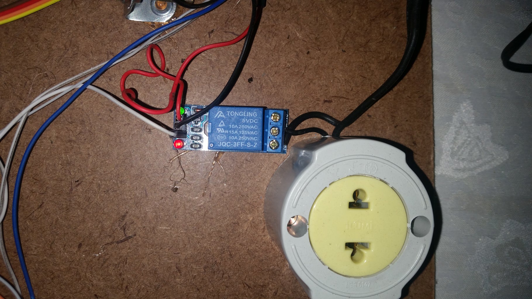
Beyond just showing a temperature, you’ll probably want to change it somehow. Maybe turn on a heater or an cooling system. In this example, I’ll use the simplest cooler possible – a table fan. This fan works on A/C 110V and uses an amout of watts much greater than an Arduino DC 5V port can delivery. To make it possible to Arduino control the fan, we’ll use a one channel relay module with optocoupler isolation.
Connect the relay module:
VCC to proto board + line
GND to proto board - line
IN to Arduino pin 13
Connect the load:
Electical appliances have two main wires: live wire and neutral wire. In some cases there’s a third one, the ground wire. It’s necessary to interrupt the live wire and make it go through the relay. Then, conect:
A/C source ground wire to fan ground pin
A/C source neutral wire to fan neutral pin
A/C source live wire to relay module COM connector
relay module NO connector to fan live pin
No library is necessary now, just define the pin used with the relay module:
// digital PINS definition:
#define Cooler      13
Inside the “setup()” procedure type:
    // pins settings
   pinMode(Cooler, OUTPUT );
And at the bottom of ‘loop’, type:
 // temperature alarm

if (Temperature > 27)  // if read temperature is greater than 27ºC
   digitalWrite(Cooler, HIGH);      // turns relay on
} else {
   digitalWrite(Cooler,LOW);       // else turns relay off
}
Test your code. If temperature is greater than 27º Celsius, relay will turn on and a indicator led on the module will light. If you connected an appliance like a fun, it should turn on.
Step 9: Push Button and Traffic Lights


A push button is probably the simplest Arduino input method, so we have to somehow use one. It will allow the user to manually control when one traffic light closes and the other one opens, like in a street crossroads.
Connect the push button, lets’ call buttons pins B1 and B2:
Connect B1 to proto board + line.
Connect B2 to Arduino pin 50.
Connect a 1K Ohm, one leg to B1, other one to proto board - line
LEDs usually have two legs and must be connected properlly:
- the long leg, called anode, goes to the positive wire
- the short leg, called cathode, to the GND.
Connect the LEDs and the resistor, use the proto board:
(first set)
Two red LEDs anodes to Arduino pin 28
Yellow LED anode to Arduino pin 30
Green LED anode to Arduino pin 32
All LED’s cathotes do one leg of a 330 Ohms resistors
The other leg of the resistor to the proto board - line
(second set)
Two red LEDs anodes to Arduino pin 34
Yellow LED anode to Arduino pin 36
Green LED anode to Arduino pin 38
All LED’s cathotes do one leg of a 330 Ohms resistors
The other leg of the resistor to the proto board - line
No library is necessary now, just define the pins used:
	//
digital PINS definition:

#define Button  50
#define Lr1     28
#define Ly1     30
#define Lg1     32
#define Lr2     34
#define Ly2     36
#define Lg2     38
And create variables:
// vars
boolean  Led1, ButtonWasPressed;
unsigned long   TimeLastPressed;
int      i;
Inside the “setup()” procedure type:
// pins settings
pinMode(Button, INPUT  );
pinMode(Lr1,    OUTPUT );
pinMode(Ly1,    OUTPUT );
pinMode(Lg1,    OUTPUT );
pinMode(Lr2,    OUTPUT );
pinMode(Ly2,    OUTPUT );
pinMode(Lg2,    OUTPUT );
// initalizes:
digitalWrite(Lr1,LOW );
digitalWrite(Ly1,HIGH);
digitalWrite(Lg1,HIGH);
digitalWrite(Lr2,HIGH);
digitalWrite(Ly2,HIGH);
digitalWrite(Lg2,HIGH);
Led1 = true;
TimeLastPressed  = millis();
ButtonWasPressed = false;
And at the bottom of ‘loop’, type:
// leds

if (OkButtonWasPressed) {
   OkButtonWasPressed = false;
   if (Led1) {  // red is on first set of leds
      digitalWrite(Lr1, LOW );
      digitalWrite(Ly1, HIGH);
      digitalWrite(Lg1, HIGH);
      digitalWrite(Lr2, HIGH);
      digitalWrite(Ly2, LOW );
      digitalWrite(Lg2, HIGH);
      delay (400);
      digitalWrite(Lr1, HIGH);
      digitalWrite(Lg1, LOW );
      digitalWrite(Lr2, LOW );
      digitalWrite(Ly2, HIGH);
      Led1 = false;
   }
   else {
      digitalWrite(Lr1, HIGH);
      digitalWrite(Ly1, LOW );
      digitalWrite(Lg1, HIGH);
      digitalWrite(Lr2, LOW );
      digitalWrite(Ly2, HIGH);
      digitalWrite(Lg2, HIGH);
      delay (400);
      digitalWrite(Lr1, LOW );
      digitalWrite(Lg1, HIGH);
      digitalWrite(Lr2, HIGH);
      digitalWrite(Ly2, LOW );
      Led1 = true;
   }
}
i = (digitalRead(Button));
if (i) {   // button was pressed
  if ((long)(millis() - TimeLastOkInterrupt) >= 500) {  // "debounces" the key
     ButtonWasPressed = true;
     TimeLastPressed = millis();
  }
}
Test your code.
Your traffic lights shoud be one “red” and the other “green” and change every time you push the button, passing by the yellow light.
Step 10: Potentiometer As Analog Input and Servo Control
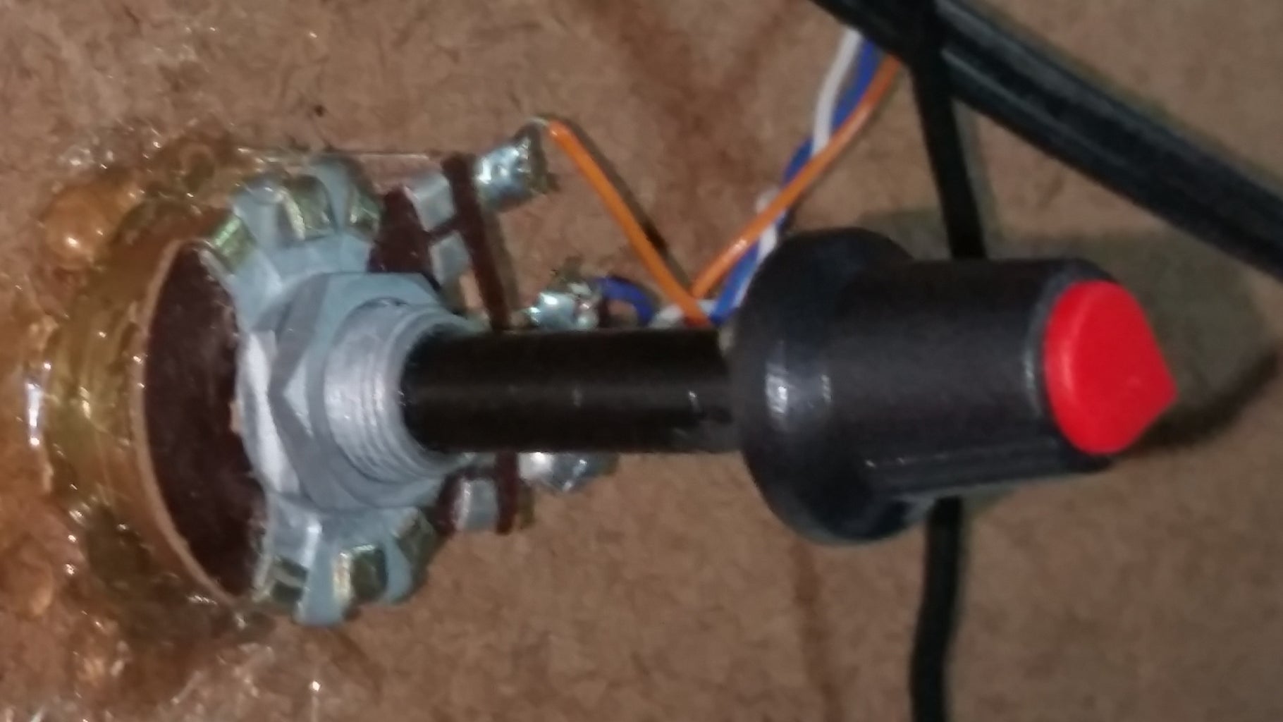

A potentiometer is a variable resistor with a terminal that can be adjusted to any value from zero to it’s max resistance. Potentiometers are widelly used, for example in the volume control of a computer’s speaker. In Arduino programming, a potentiometer may be used as a analog input, but to represent digital values. The function “map” allows you to re-map a number from one range to another, for example let’s say the potentiometer min returned value is 5 and the max is 900, but we need to translate this values to the range 0~180, the map function will be:
result = map (ValueRead), 5, 900, 0, 180);
In a simplified view, a standard servo is a motor that is able to position the shaft at various angles, usually between 0 and 180. Arduino libraries allow the programmer to tell the servo to wich angle it must move and stay there until the next command.
Connect the potentiometer:
Connect the right terminal to proto board + line.
Connect the left terminal to proto board - line.
Connect the midle terminal to Arduino pin 1.
Connect the servo:
Connect the black wire from the servo to the GND pin on the Arduino.
Connect the red wire from the servo to the +5V pin on the Arduino.
Connect the yellow or white wire from the servo to a digital pin on the Arduino.
Connect the red wire to proto board + line.
Connect the black wire to proto board - line.
Connect wire left to Arduino pin 51.
Define the servo’s library:
#include <Servo.h>
Define the potentiometer pin:
// analog PINS definition:
#define Potentiometer   1
Define the Servo pin:
// digital PINS definition:#define
ServoPin 51
Declare the servo object:
Servo myservo; // create servo object to control a servo
Inside the “setup()” procedure type:
myservo.attach(ServoPin); // attaches the servo on pin defined by ServoPin
And at the bottom of ‘loop’, type:
i = analogRead (Potentiometer);
i = map((i), 5, 890, 0, 180); 	// converts value read to angle
				// adjusted for a 5K linear potentiometer
myservo.write(i);
Test your code. Your servo shoud move as you rotate the potentiometer’s shaft.
Step 11: Conclusion
I hope this instructables may be helpfull both on showing how sensors and actuators may be used with arduino and on helping with some examples.
Sources:
https://forum.arduino.cc
https://github.com
http://herlaar.net/b3it/b3it-kit/sensors-and-actua...
https://www.diffen.com/difference/Analog_vs_Digita...
https://tinkerlog.com/2009/04/05/driving-an-led-wi...

Participated in the
Arduino Contest 2017

![Tim's Mechanical Spider Leg [LU9685-20CU]](https://content.instructables.com/FFB/5R4I/LVKZ6G6R/FFB5R4ILVKZ6G6R.png?auto=webp&crop=1.2%3A1&frame=1&width=306)


