

Introduction: Arduino Shooting Game V3


This game is for you that use airsoft or co2 to shoot at targets. It's a game.
For up to date info about the game and support:
https://www.facebook.com/arduinoshooting/
For my blog page about the game:
https://shootinggameblog.wordpress.com
For the codes about the game:
https://github.com/shootinggame82/Shooting-game-v3
Shooting game is x targets that are wireless, each target has an vibration sensor that sens vibration that gets when a hit is made. The wireless sensors is an Atmega328 chip (Arduino Uno chip) and have recharge Li-Po battery.
The Main controller for this game is controlled by an Arduino and is Serial controlled from an Raspberry Pi.
So how is this game working ?
Well it's 3 game modes:
Quicktime: Play X rounds and shoot so fast you can on each target.
Timemode: Shoot as many targets you can on X seconds.
Rapidfire: Shoot X shots on the quickest time.
The system us NRF24L01 transmitters to get a good distans from the main controller. They work on 2.6 GHz (The same as WiFi runs on)
In my past projects i have been using Piezo for the vibration, but now Vibration Sensor Switch are used.
But you can still use Piezo if you have made my old version of this game.
The game has an Raspberry Pi 7" touch screen that holds the web system that you control the game thru.
An terminal printer prints out the results.

Supplies
For transmitters:
- X Atmega328 with Arduino Bootloader (Depending on how many targets)
- X Vibration Sensor Switch
- X Blue Led
- X Green Led
- X Red Led
- X 3.7v Li-Po battery
- X FC-75 Li-Po Charger module (Or another model)
- X 100 uF Capacitor
- X Cases for the sensors
- X LD1117V33 (Makes a safe 3.3 V to transmitter)
- X NRF24L01 Modules
- X x 3 220 Ohm Resistors (3 is needed for one target)
- X 16 MHz Crystal
- X x 2 Unplorized Capacitors 22 pF (2 is needed for one target)
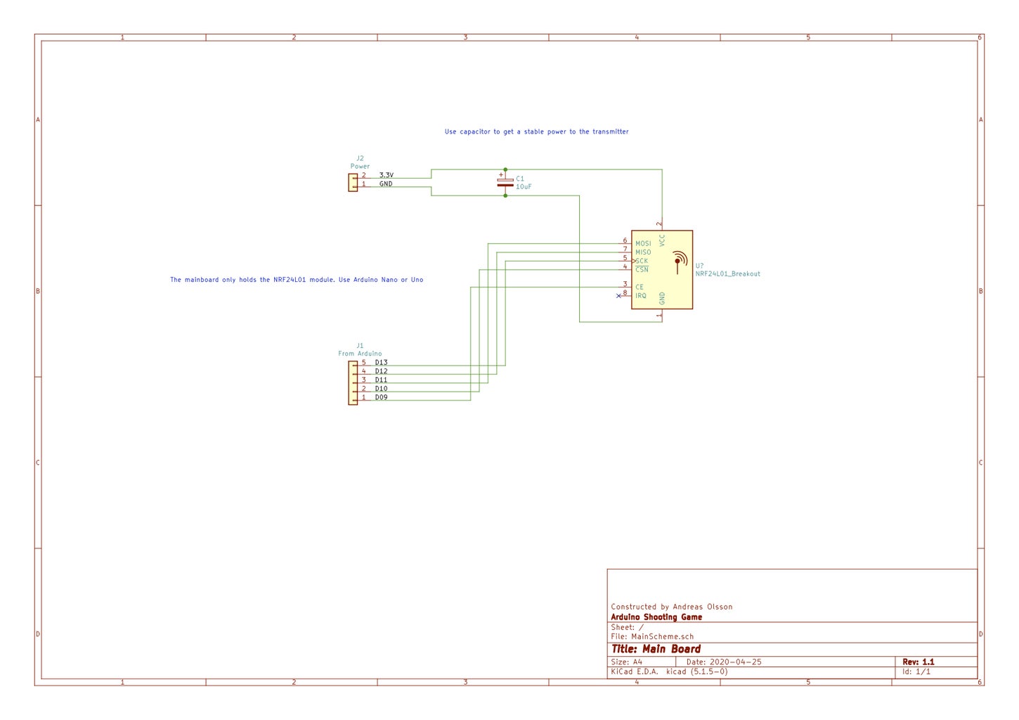
For main Arduino:
- 1 Arduino (Nano or Uno is recommended, need to have USB)
- 1 NRF24L01 Module
- 1 10 uF capacitor
For raspberry Pi:
- Raspberry Pi (I used 3B)
- 7" Touch Screen
- ATXRaspi (Optional but a good power button module)
- RTCRaspi (Optional but a good RTC module to keep time and date)
- Termal printer (Optional but needed to be able to print)
- Barcode scanner (USB version that works like an keyboard, Optional)
- Good 5V power (I used an old 12v USB with 2.5 A power)
Other stuff:
- 12v power (I have one at 12 Ah)
- Network socket (Make it easy to connect to Network)
- Cables
Step 1: The Wireless Sensors


Let's start making the sensors.
I use 4 sensors for this game. But you can easy add more sensors.
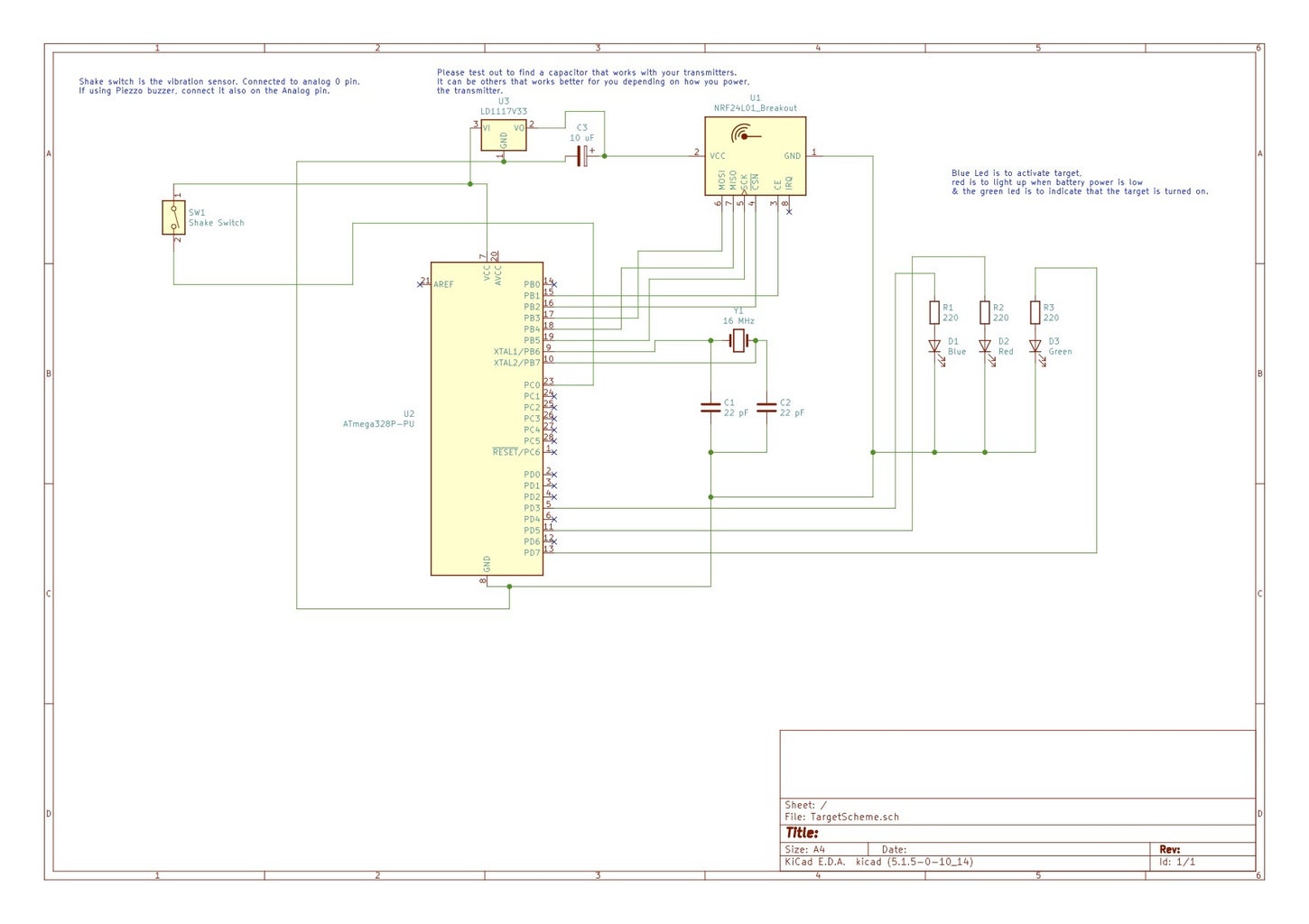
The sensors is communicate with 4 numbers code when the main system send out the code with what function the sensor with the right code will light up and be ready for the target. The blue light is to inform that it's that target that you are going to hit.
We also has a green and a red led. The green always lights up to inform that the sensor is on. The red will only light up when the battery is less under 3.1V (it uses the built in function in the chip to calculate how much there is in the battery.
The vibration sensor is connected to the analog pin and reads its value. When the value is sinking, the sensor has pic up an vibration and that is where we registrate the hit.
The target has a failsafe function, that incase you don't hit in X seconds (default is 15 sec) or if the transmitting can't be done in they will go back to start position.
I'm not going to explain how you are going to wire, check the electric sheet to se how you are going to do that.
The one thing that is not on it, is the battery, power switch and the charger. That is up to you to decide how you want it.
IMPORTAINT ABOUT THE NRF24L+ Module:
It can be pain in the ... to get them stable, combined with good power and isolation around it, and the code you will get them to work. For me 10 uF capacitor will give me stable and good connection, but please try first incase you need for example 100 uF capacitor. Also wrapt them with first plastic foil and then Aluminum foil to protect them from interfering.
Also in the code, the data rate you don't need more than 250 Kb so that will not be the problem. But the PA: myRadio.setPALevel(RF24_PA_MIN);
In the code I have set to MIN (This is during test), it's the lowest and will not use so much power, but the range will not be so long. If you got stable and good power to them, you can go up to RF24_PA_MAX to get the longest range, BUT they need GOOOOOD stable power for that. Try also LOW AND HIGH (Change MAX text only) to see if you get good communication. Also you will get good range on LOW and HIGH unless you are going to be a sniper.
Also keep the transmitters at least one meter apart, to close can make the signal bad!
Test the communication with some ping example in the NRF24 Library (Link on GitHub)
In the code you need to set the unique identification number for that target:
int targID = 3401; //This is the target ID
int sendID = 2401; //This is the response ID
There is also 3 DEFINE functions:
#define DEBUG
#define BATTERY
#define SHAKE //IF SHAKE SWITCH IS USED INSTEAD OF THE OLD PIEZO
DEBUG:
During test this is good to have defined. But when you are make them available, don't have it activated.
BATTERY:
If you don't want to have a battery checker for the targets, you need to remove this define.
SHAKE:
If you have build my old version, you have piezo sensors, then remove this to get correct code for them.
ATMEGA328 Chip
Instead of an Arduino nano I decided to use ATMEGA328 chip (with Uno boot loader), they are simple to program just remove the chip from an Arduino Uno and add this chip and upload code. Check the electric scheme on how to build the targets.
The Code
I have written the code with PlatformIO instead of Arduino IDE. It's a better software to program in. So the code is a little different. I recommend to use this software instead.
The Target & Transmitter Box
I have attach the sensor and the blue led on the target, and with a 3,5 mm phono cable on 2 m i connect it together in the transmitter box that holds the atmega chip, battery charger and the green & red led. This is so to protect it from being hit with steel bullets.
Attachments
Step 2: The Game Controller


The next thing we need to do is to make the controller for the sensors. It's an Arduino that uses an NRF24L01 module to communicate with the sensors. Nothing else. The Arduino is then connected with USB in the raspberry pi to work.
This is how it will work. It uses serial to know what to do.
The pi will send out serial commands. First during setup it sends out how many targets you have added, and the targets identification numbers. Then it will do the test function and inform the raspberry pi if they do communicate with each other.
When you play the game it will send over from pi what type of game and how many rounds/hits to use. Thats it.
It is possible to use the NRF24L01 modules in the raspberry pi, but for me the Arduino is a better option sins I never use them in raspberry so I don't know how good they work in the long term.
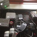
There is a power module that uses 5 v to make correct stable power to the transmitters. You can use them with you Arduino (See the picture) the name is Socket Adapter Module Board
When you play the targets will be randomly activated one by one. When one is hit, another one will be activated.
During the test you can have #DEFINE DEBUG activated to see how it works, but not when you use it in the pi computer, it will not work then.
Download the code on the GitHub page.
Attachments
Step 3: Raspberry Pi


We have now come to the Raspberry Pi.
I have added some extra functions so i can have an power button. The ATXRaspi 3 is a great module, you can turn on, off and reboot the pi with a button. Also an RTCRaspi to keep the time and date on the pi. Also made it possible to just plugin a network cable incase i need to do some updates on the system. You will find them on Lowpowerlab
The Thermal printer you will find on sparkfun and the barcode reader is available on amazon.
The Pi computer runs in kiosk mode so the browser will open up at start.
First of all you need to have an webserver with PHP 7 and mysql on the pi computer. (There are a lot of guides around the web for this)
PLEASE NOTE : if you are going to use thermal printer with raspberry pi that has built in bluetooth you need to disable that one first.
The python script needs pyserial and you install it: sudo apt-get install python-serial
To make the mysql work install following:
sudo apt-get install mysql-python
sudo apt-get install python-mysql.connector
suso apt-get install pymysql
Now you can control you Arduino thru serial and also update the mysql database.
Next step is to make python script to connect to mysql.
In all three python script change the connection to your mysql database.
Next step is to make the python script run at start.
There are three python script.
game.py is the most importaint of all, that one holds the game function.
print.py this is only needed if you are going to use termal printer to print.
ean.py is only needed if you are going to use the barcode scanner.
To make them autostart i edit:
sudo nano /etc/rc.local
and add following at bottom before exit 0 :
sudo python /home/pi/Gamefiles/game.py &
sudo python /home/pi/Gamefiles/print.py &
sudo python /home/pi/Gamefiles/ean.py &
Please change to correct place for your python script and don't forget the & sign at the end.
Now we need to make a kiosk mode for the webbrowser, first remove the cursor:
sudo apt-get install unclutter
sudo nano /etc/xdg/lxsession/LXDE-pi/autostart
now in that file find and comment out:
@xscreensaver -no-splash # comment this line out to disable screensaver
Below that add:
@xset s off @xset -dpms @xset s noblank @chromium-browser --noerrdialogs --force-device-scale-factor=1.25 --kiosk http://localhost
Next step to remove all boot texts and stuff also add your own boot screen here is a quick guide:
sudo nano /boot/config.txt and at bottom adddisable_splash=1
Remove text message under splash image:
sudo nano /usr/share/plymouth/themes/pix/pix.script
Find and remove (or comment out):
message_sprite = Sprite();
message_sprite.SetPosition(screen_width * 0.1, screen_height * 0.9, 10000);
and:
my_image = Image.Text(text, 1, 1, 1);
message_sprite.SetImage(my_image);
Now we remove boot messages:
sudo nano /boot/cmdline.txt
replace “console=tty1” with “console=tty3”
and at the end of line add:
splash quiet plymouth.ignore-serial-consoles logo.nologo vt.global_cursor_default=0
And replace the pi splash with your own:
sudo cp ~/my_splash.png /usr/share/plymouth/themes/pix/splash.png
Now you have your own custom boot screen to your game. Your pi computer is now ready to handle the game.
So over to next step!
Step 4: Setup the Game
At this point you have now created the game.
First you need to do is to setup the webbsystem. Upload the database to your mysql server. The file is in the includes folder and named database.sql
Next step is to edit the config file, you find it in the includes folder name config.php
Change the database login information so the script will work.
The web system is multi language based and is written in English. There is an Swedish translation available.
To make more language you need a software named Poedit.
To add more language to the web system you need to edit i18n_setup.php and add in the array:
return in_array($locale, ['en_US','sv_SE']); (Line 23)
Also to change the default language you need to change in line 27: $lang = 'en_US'; change the en_US to you language.
the language files must be placed in locales/LANGCODE/LC_MESSAGES/ and be named main.mo (Change langcode to you language)
to change the keyboard in file selectplayers.php you change language : "en", //en for english sv for swedish layout : 'qwerty', //qwerty for english swedish-qwerty for swedish
You find them on line 218 & 219
The available languages are in folder: assets/js/keyboard/languages & layouts are in assets/js/keyboard/layouts and add the correct files to line 118 and 119 (replace the one you find there now)
Add targets
To add targets you go to localhost/admin/ and click on add targets.
You need to add a name for the target and the unique target ID and send ID, add as many targets that you have.
Add games
You also need to add some games. Go to localhost/admin/ and click on add game
You need to add a name for the game, a description, min and max players what type of game, also how hard the game is between 1 to 5. And how the game is, so for the rapidfire game you add how many hits (example 30) for the quickdraw how many rounds (for example 8) and for timed how long they are going to play (for example 60 for one minute)
Start the game
When you power up the game it will do the target testing. So the targets need to be on before you start the main system. If all passes the test you can use the system, but if they don't you can't use it. It will try to communicate until they got response.
Good luck!
Well that's about it, for support and info about update in the code please follow my Facebook page for this game, so I can give you response fast. You will find links in top here.


