

Introduction: Arduino Street Traffic Light - Breadboard Edition


Build a simple Arduino powered Traffic Light with us! This instructable is meant to walk you through almost every step, but there are a few assumptions. Read over the intro and the first step to make sure you are fully prepared! This is the breadboard version, a more realistic traffic light will be generated soon. Please leave comments - tell us if things are confusing!
Supplies Needed:
1 x Computer with Internet Access
1 x Arduino Uno
1 x USB A/B Cable for connecting the Arduino to your PC
1 x Breadboard (Half-Size, with Voltage Rails)
1 x Red LED
1 x Yellow LED
1 x Green LED
3 x 100 Ohm Resistors (Brown Black Brown)
4 x Breadboard Wires (22 AWG, approx. 6+ inches in length)
Other Helpful Things:
- Good lighting
- A clean workspace
- An hour of your time
- Someone awesome to work with
Missing Something?
- Check out hackerspaces.org for a local place for tools, supplies, etc.
- Near Ann Arbor, MI? We have all the supplies needed to do this instructable at our hackerspace "All Hands Active"
- Radioshack, AdaFruit, SparkFun, Jameco, are just a few resources that will have all the needed items.
You wanted a smarter traffic light?
- That's our next instructable, stay tuned!
Step 1: Set Up the Arduino Environment

This instructable makes many assumptions! Some people like to call these "prerequisites". In order to make sure you get the most out of this instructable, you should have:
- The Arduino Software downloaded and installed on your computer.
- Plugged in and tested your Arduino by following the installation guide appropriate for your computer.
- Approximately one hour of time to spare, and a nice clean workspace with plenty of lighting.
Mission Complete? Continue on!
Image Source: The Getting Started w/Arduino Guide
Step 2: Wire Your Green LED


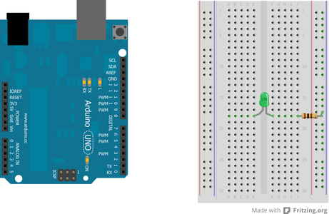


Situate your Arduino on the left, and your breadboard on the right! If you have not used a breadboard before, it's a bit like playing Battleship. If you haven't played Battleship, that's okay : )
For this step, you will need:
1 x Arduino Uno
1 x Breadboard (Preferably Half-Size with Voltage Rails)
1 x 100 Ohm Resistor (Brown Black Brown)
2 x Breadboard or Jumper Wires (22 awg approx. 6" long)
1 x Green LED
Onward!
Breadoards are great, and they come in all shapes and sizes. They make it easy for you to prototype an electrical circuit without having to solder connections together. Don't worry if yours is a little different. If it comes with voltage rails, then it should be pretty easy to follow along. If it doesn't, you will have to figure out an alternate way to supply power.
Voltage rails are the two columns that run along the left and right sides of the breadboard pictured above. These are used to make it easier to bring power to various points throughout your breadboard. We will ground all of our connections along the right, or "blue" labeled voltage rail. In the step above, w connect a black wire running from the "GND" pin of the Arduino, to a voltage rail..
Digital, Analog The Arduino has 14 Digital pins, and 6 Analog pins. A Digital pin can operate in two ways: On, also known as "HIGH", and Off, otherwise known as "LOW". When a Digital Pin is set to On, 5 volts of electricity are running through it. When it's set to Off, no voltage runs through it. This will make it easy for us to turn an LED on or off. These pins are represented as "DIGITAL", pins 0 through 13 at the top right of the Arduino pictured above.
Analog pins can operate differently. Instead of being limited to on or off, they can read a range of values from between 0 Volts and 5 Volts, but they convert "volts" into whole numbers, specifically 0 through 1023. For example: 0 = 0 Volts, 512 = ~2.5 volts, and 1023 would mean 5 volts. These pins are represented as "ANALOG IN", pins 0 through 5 at the bottom right of the Arduino pictured above.
Resistors do exactly as they say, they resist! But what? Electrons! Too much power, or current and we can ruin our LED, so we include a resistor in line with it. We measure resistance in units called "Ohms". The resistor we are using provides 100 Ohms of resistance. The colored strips Brown (1), Black (0), Brown (add 1 more 0), are how we identify what the value of our resistor is.
Follow the images to complete this step, then move on to the next step to get your LED turned on!
Step 3: Turn on Your Green LED

The Setup function runs once when the arduino is turned on.
The Loop function runs continuously after the setup function runs once.
For you to turn on your LED, two things must happen.
First, you must tell the pin that you plugged in your LED to (in this case, PIN 3) to be in OUTPUT mode. This tells the pin that you're going to send data out to it. You can set your pin to be in output mode using the pinMode function.
Second, you must tell the pin to be in HIGH mode. HIGH mode sends a high electrical signal through the pin. LOW mode sends a low electrical signal. You can set your pin on high mode by using the digitalWrite function.
// basic functions
voidsetup()
   {
// setup LED modes
// we're specifying that we're going to send information to this LED
pinMode(3, OUTPUT);
   }

voidloop()
   {
// High turns things on
digitalWrite(3, HIGH);
   }
Step 4: Use a Variable

pinMode(3, OUTPUT);Once we start adding more LEDs, we're going to have lots of pin numbers everywhere. Keeping track of these pin numbers will become more and more annoying and hard. BUT! Fear not! Programming languages offer a wonderful solution:Variables
Variables allow you to give names to things. There are lots of different types of variables.
Today we're going to learn about a number variable called an int (short for integer). An int can be any whole number from -32,768 to 32,767.
Variables have 3 properties: type, name, and value.
For instance:
int GREEN = 3; has a type of int, a name of GREEN, and a value of 3.A variable is used in place of a value.
Anywhere you want to use a "3," you can now write "GREEN."
* Remember: You have to make a variable before you can use it!
* Variables exist in different areas known as scopes. A scope is the area between a starting curly bracket { and its matching ending curly bracket }. In our case, we're going to declare the variables all at the top of the code. These variables are known as global variables. A global variable can be used anywhere in the document.
Example:
// variables
int GREEN = 3;

// basic functions
voidsetup()
   {
// setup LED modes
// we're specifying that we're going to send information to this LED
pinMode(GREEN, OUTPUT);
   }

voidloop()
   {
// High turns things on
digitalWrite(1, HIGH);
   }
Step 5: Make Your LED Blink!

Combining the delay function with the loop function allows us to create a blinking effect with the LED.
We will do this by setting a delay of 1 second (1000 milliseconds) between the LED being on (HIGH) and the LED being off (LOW).
We're going to use an int variable named DELAY so that we can change its value without having to type in numbers over and over everywhere.
Example:
// variables
int GREEN = 3;
int DELAY = 1000;

// basic functions
voidsetup()
   {
// setup LED modes
// we're specifying that we're going to send information to this LED
pinMode(GREEN, OUTPUT);
   }

voidloop()
   {
// High turns things on
digitalWrite(GREEN, HIGH);
delay(DELAY);
// low turns things off
digitalWrite(GREEN, LOW);

   }
Step 6: Wire Your Yellow LED!


In this step we will be adding a second LED. You will be 2/3rds of the way to having a completed Traffic Signal!
For this step, you will need:
1 x 100 Ohm Resistor (Brown Black Brown)
1 x Breadboard or Jumper Wires (22 awg, approx. 6" in length)
1 x Yellow LED
Step 7: Make Both LEDs Blink!

For this step, repeat the same steps as the step to set up the Green LED.
* Remember to set both LEDs to OUTPUT mode!
* Remember to turn off one LED when the other one is on!
Can you set it up so that your Green LED stays on for 5 seconds and your Yellow LED for only 2 seconds?
Example:
// variables
int GREEN = 3;
int YELLOW = 4;
int DELAY_GREEN = 1000;
int DELAY_YELLOW = 1000;

// basic functions
voidsetup()
   {
// setup LED modes
// we're specifying that we're going to send information to this LED
pinMode(GREEN, OUTPUT);
pinMode(YELLOW, OUTPUT);
   }

voidloop()
   {
// High turns things on
// Low turns things off
digitalWrite(GREEN, HIGH);
digitalWrite(YELLOW, LOW);
// how long we want the green led on
delay(DELAY_GREEN);

digitalWrite(GREEN, LOW);
digitalWrite(YELLOW, HIGH);
// how long we want the yellow led on
delay(DELAY_YELLOW);
   }
Step 8: Wire Your Red LED!


We'll be wiring up your final LED in this step. Hopefully you have a good idea at this point how we'll go about doing this! Mouse-over the caption box in the image for details on where to connect everything.
For this step, you will need:
1 x 100 Ohm Resistor (Brown Black Brown)
1 x Breadboard or Jumper Wires (22 awg)
1 x Red LED
Step 9: Make All the Lights GO!
For this step, set up the Red LED the same way as the Yellow LED.
* Remember to all LEDs to OUTPUT mode!
* Remember to turn off two LEDs when one is on!
Can you set it up so that your Green LED stays on for 5 seconds and your Yellow LED for 2 seconds and then your Red LED for 5 seconds?
Example:
// variables
int GREEN = 3;
int YELLOW = 4;
int RED = 5;
int DELAY_GREEN = 1000;
int DELAY_YELLOW = 1000;
int DELAY_RED = 1000;

// basic functions
voidsetup()
   {
// setup LED modes
// we're specifying that we're going to send information to this LED
pinMode(GREEN, OUTPUT);
pinMode(YELLOW, OUTPUT);
pinMode(RED, OUTPUT);
   }

voidloop()
   {
// High turns things on
// Low turns things off
digitalWrite(GREEN, HIGH);
digitalWrite(YELLOW, LOW);
digitalWrite(RED, LOW);
// how long we want the green led on
delay(DELAY_GREEN);

digitalWrite(GREEN, LOW);
digitalWrite(YELLOW, HIGH);
digitalWrite(RED, LOW);
// how long we want the yellow led on
delay(DELAY_YELLOW);

digitalWrite(GREEN, LOW);
digitalWrite(YELLOW, LOW);
digitalWrite(RED, HIGH);
// how long we want the red led on
delay(DELAY_RED);
   }
Step 10: Use Functions!

In the previous step, we wrote the following lines of code:digitalWrite(GREEN, HIGH);
digitalWrite(YELLOW, LOW);
digitalWrite(RED, LOW);
Once we start having more complex programs, we're going to have lots of steps. Putting a space between steps makes the program a little more readable; using Functions make the program even more readable.
Functions allow you to group instructions. Functions have 3 main parts. Input, instructions, and output!
Today we're going to focus on just the grouping of instructions!
Functions are just like variables. Once your create them, you can replace the sets of instructions you put into the function in the rest of your program.
Turning this set of instructions:void loop()
{
digitalWrite(GREEN, HIGH);
digitalWrite(YELLOW, LOW);
digitalWrite(RED, LOW);
}
Into this:void loop()
{
green_light();
}void green_light()
{
digitalWrite(GREEN, HIGH);
digitalWrite(YELLOW, LOW);
digitalWrite(RED, LOW);
}
A function is used in place of instructions.
Anywhere you want to make a green light, you can now write green_light();.
* Remember: You have to make a variable before you can use it!
* Variables exist in different areas known as scopes. A scope is the area between a starting curly bracket { and its matching ending curly bracket }. In our case, we're going to declare the variables all at the top of the code. These variables are known as global variables. A global variable can be used anywhere in the document.
Example:// variables
int GREEN = 2;
int YELLOW = 3;
int RED = 4;
int DELAY_GREEN = 5000;
int DELAY_YELLOW = 2000;
int DELAY_RED = 5000;
// basic functions
voidsetup()
{
// setup LED modesv // we're specifying that we're that
// we're going to send information to this LED
pinMode(GREEN, OUTPUT);
pinMode(YELLOW, OUTPUT);
pinMode(RED, OUTPUT);
}
voidloop()
{
green_light();
delay(DELAY_GREEN);
// code to make a yellow light
delay(DELAY_YELLOW);
// code to make a red light
delay(DELAY_RED);
}
void green_light()
 {
digitalWrite(GREEN, HIGH);
digitalWrite(YELLOW, LOW);
digitalWrite(RED, LOW);
 }
void yellow_light()
{
// your code here
}
void red_light()
{
// your code here
}
//
Step 11: Sending and Receiving Information!
The steps following this will enable communication to and from our Traffic Light! The code for this part is not yet accessible, but feel free to adventure on!
Step 12: Adding an Infrared LED


An infrared (IR) LED functions just like a normal LED, but humans are typically unable to see light emitted from these. We will be using an IR LED to communicate to our line following vehicle whether or not the Traffic Light is Red or Green. If the Traffic Light is Red, then the IR Light will also be on.
Mouse-over the caption box in the image for details on where to connect everything.
For this step, you will need:
1 x 100 Ohm Resistor (Brown Black Brown)
1 x Breadboard or Jumper Wires (22 awg)
1 x IR LED
Step 13: Adding an IR Receiver


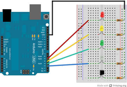
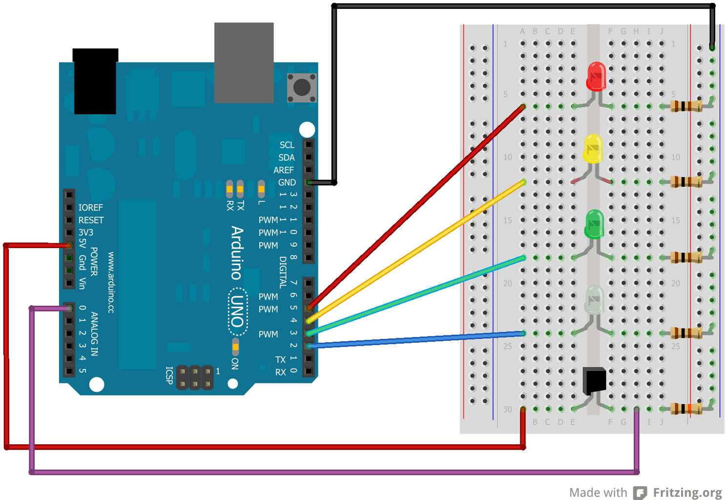
An infrared receiver detects infrared light! We will use it to detect the presence of our line following vehicle. This will allow us to either decrease the amount of time the Traffic Light is Red, or increase the time the Traffic Light is green..
Mouse-over the caption box in the image for details on where to connect everything.
For this step, you will need:
1 x 10k Ohm Resistor (Brown Black Orange)
3 x Breadboard or Jumper Wires (22 awg)
1 x IR Receiver


