

Introduction: Arduino Time Lapse Slider


so i had been looking into making a timelapse video with my dslr and had seen many using a slider mechanism to add another dimension. I looked at buying one but they are a little expensive to buy just to "dip ones toes into the water" so to speak. i had a lot of the bits from an arduino starter kit i had bought so i decided to attempt to make one.
this is what i did....
Step 1: Home Made (sort Of) Arduino Timelapse Slider
given that the sliding mechanism needs to be reasonably smooth as well as sturdy i decided to keep an eye out for that part of the mechanism on ebay i managed to find a 500mm slider for a little over £30 and this was the most expensive part of the whole exercise. the next thing a realised was it would not be a good idea to stick external voltages through my £800 camera body's remote trigger input. so i elected to use an opto isolator, this is a kind of electronic relay but would require far less power from the arduino side of things.
so to start let's get a list of materials
- slider kit, like this one
- belt and pully kit, like this one
- stepper motor and driver, like this one
- arduino pro mini or arduino uno, like this one (ensure 5v)
- remote control and ir sensor, like this one (may need to play with code to match buttons layout)
- 1602 lcd display with i2c module, like this one
- LED to indicate camera trigger (optional)
- 4N35 or equivalent opto isolator this search will reveal how this works as well as suggesting alternatives
- old usb lead for power, lead for remote operation of camera.
- push to make button for stopping and n/o micro switches for limit (optional)
Step 2: Wiring Arduino Slider Programming and Testing
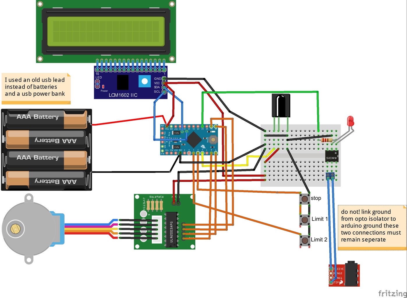
so now having waited for China post and hopefully having a full list of materials we can start assembling the wiring as per the diagram above, taking care to ensure that the cameras remote trigger remains isolated from all other parts of the circuit i also used a usb lead instead of the AA's and a usb power bank this gave me a regulated 5v supply for the arduino and the stepper motor.
now we will need to upload the code to the arduino, you will need the following libraries to complete the upload
- Stepper.h
- IRremote.h
- Wire.h
- LiquidCrystal_I2C.h
some are included in the default install of the arduino ide
if the upload completes successfully then you should new be able to control the stepper motor with the jog buttons to reset its travel set its step speed with the number buttons and increase and decrease the delay with the + and - buttons, i have set a minimum of 1 sec and a maximum delay of 10 seconds this could be adjusted easily in the code and i have added notes so you can find the part that would need changing. i have also set the movement speed to be adjustable from around 1mm to 5mm again this could be easily customised within the code also.
Attachments

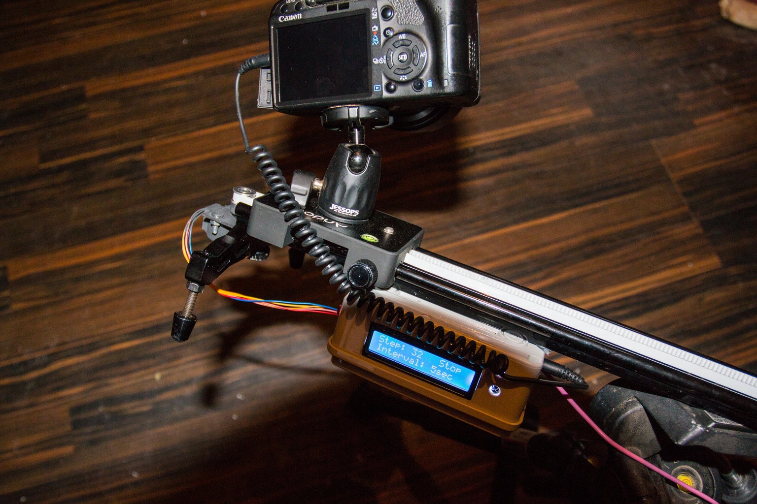
Step 3: Final Build
now things are working we can assemble the device. i had to get creative and make two brackets from some old pieces of steel to support the stepper motor and jockey pulley and then create a bracket to hold the belts two loose ends to the carriage with the correct tension. i found an old enclosure to place the workings in and attach the lcd display and buttons, i made a small hole for the ir sensor and connected the usb lead and camera trigger lead to the electronics.
you can see more examples and sample shots of the device at the link below.
https://app.keenai.com/s/30532839-2-rxd7BT7kYluWonpw
let me know if you have any questions or suggestions.
further examples of my time lapse videos created with this device can be found on my youtube channel here.

Participated in the
First Time Author Contest 2016


