

Introduction: Arduino Tutorial - BLYNK Styled Button and ESP-01 Relay Module


Welcome to another tutorial on our channel, this is the first tutorial of this season that will be dedicated to IoT systems, here we will describe some of the features and functionalities of the devices used in this type of systems.
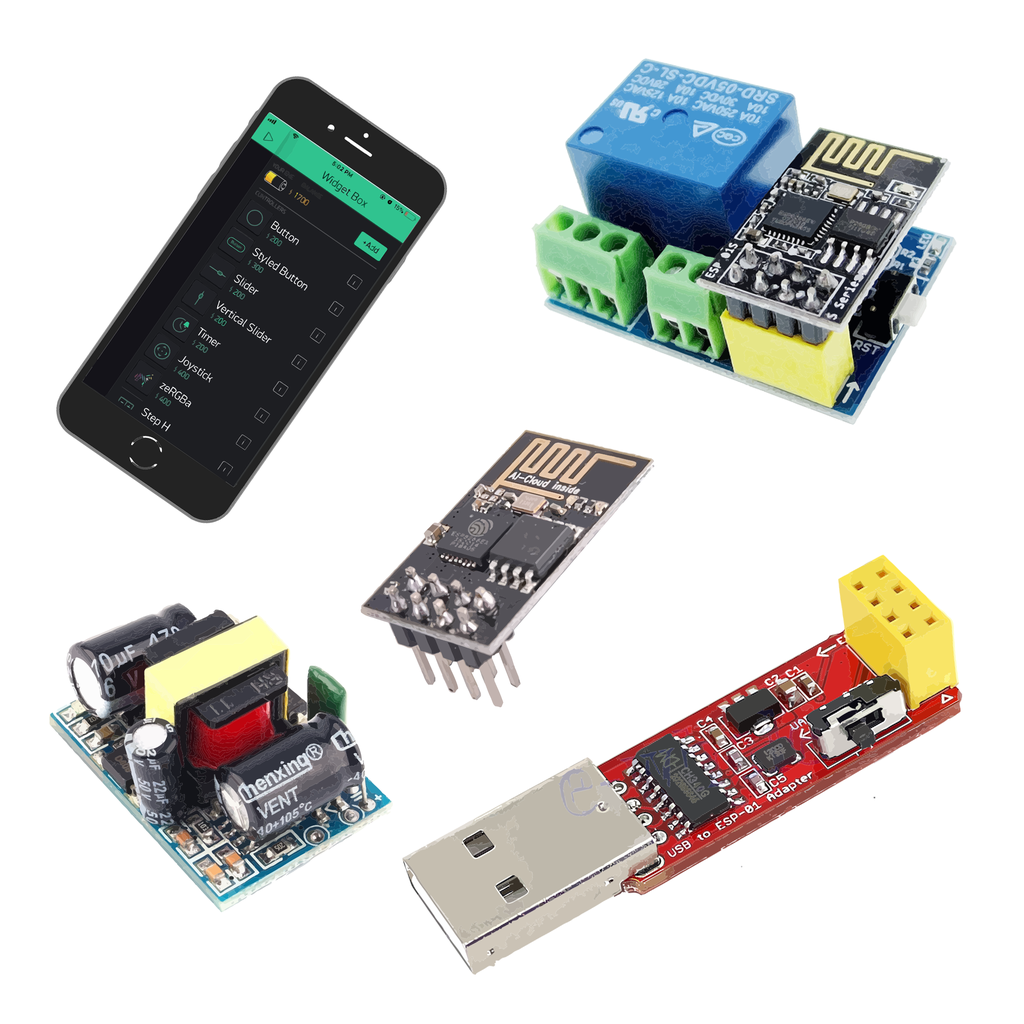
To create these systems we will use the Blynk App designed for IoT systems and it is a very easy and intuitive application to work with (See the image above). This App has already been mentioned in previous tutorials, but this season we'll describe in detail the most important features of each of its widgets.
Blynk IoT Plataform site: https://blynk.io/
With this application we can use interfaces that control and view the data generated from a physical device remotely, just have that device and a smartphone connected to the Internet.
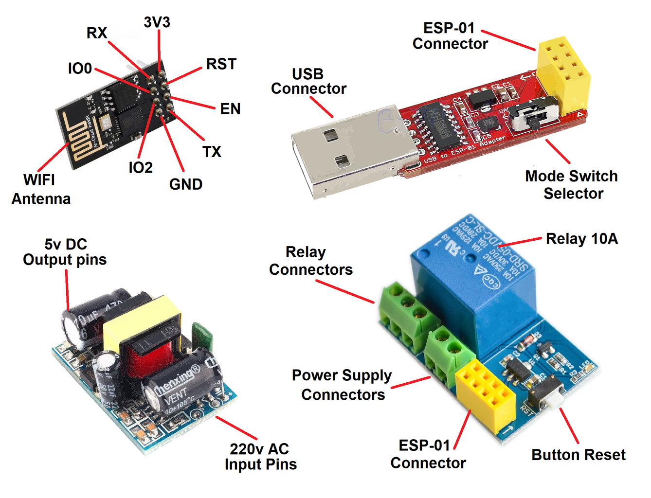
This physical device will have a relay that will control a simple lighting system and this relay will be connected to a very small and simple Wi-Fi control device, this device is the ESP8266 ESP-01 module (see datasheet below).
This equipment stands out for its small size, low price and versatility.
In the previous tutorials we used several different types of Arduino boards and these were always the main devices of the assembly and contained the programming code, controlling and managing all the features.
In the last tutorial, the ESP8266ESP-01 module was used only as communication device, receiving and transmitting only Wi-Fi data and not as main assembly equipment.
Arduino Tutorial - Blynk Motor Speed Control ESP8266:
https://www.instructables.com/id/Arduino-Tutorial-Blynk-Motor-Speed-Control-ESP8266/
This time the main device will be the ESP8266 ESP-01 module, which will control and manage all the assembly resources.
ESP8266 ESP-01 module specifications:
- Tensilica Xtensa integrated CPU of low power and 32 bits;
- 1MB Flash memory;
- SPI, UART and SDIO communication protocols;
- Connection - 8 pin connector;
- Digital I/O pins (PWM) - GPIO0 and GPIO2;
- Input voltage: 3.3V DC;
- Wi-Fi PCB antenna on board;
- Size - 25x14x1mm;
Another module that is also very useful when creating projects in IoT systems is the Relay module. This module is designed to work together with the ESP-01 module and also has a very easy to use 8 pin connector (see data sheet below).
ESP-01 Relay module specifications:
- Operating voltage: 5V DC;
- Load relay - 250V AC - 10A;
- Connection - 8 pin connector;
- GPIO0 pin for relay control (high level status);
- Size - 37x25mm;
As the assembly devices are not energized at the same values as the table lamp, a more appropriate power supply is required.
Although the ESP-01 module requires a different supply voltage than the Relay module, a different power supply will not be required because the ESP-01 module is energized directly through the Relay module (see image below).
Power Supply specifications:
- Input voltage: 230V AC 50Hz;
- Output voltage: 5V DC;
- Output current: 700mA;
- Power: 3,5W;
- Short-circuit protection;
- Temperature protection;
- Overload protection;
- Size: 30x20x18mm;
As can be seen easily, the ESP-01 module has many advantages, but in contrast to other card models already mentioned before, this module does not allow connecting directly to a computer to load the programming code.
For this reason, an adapter device is needed to guarantee this connectivity, if possible through the USB plug (see image below).
ESP-01 USB adapter module specifications:
- USB-Serial connection;
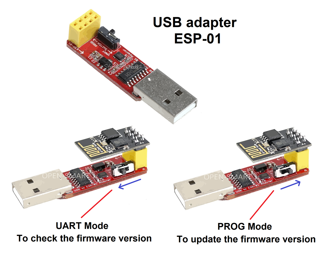
- Mode switch On-board - Communication (UART) and Program (PROG);
- 3,3V DC regulator circuit On-board,
- Size: 49x17x10mm;
It is very easy to find this module on the market, but be careful, there are USB adapter modules without this switch and if you buy it you should make a small modification, but you will need some skill (See link below).
USB to ESP-01 Adapter Board Modification: https://www.instructables.com/id/USB-to-ESP-01-Board-Adapter-Modification/
If you don't want to buy this USB Adapter module, there is another method to connect the ESP-01 module to your computer. This method uses only a Breadboard and an Arduino UNO, however, this method is not as practical as an adapter module (See link below).
Arduino Tutorial - Blynk Motor Speed Control ESP8266:https://www.instructables.com/id/Arduino-Tutorial-Blynk-Motor-Speed-Control-ESP8266/

Step 1: Circuit Assembly


The assembly of this tutorial is very simple, just connect all devices to each other and most of your connections will be used (See the image above).
Part list:
- 1x ESP8266 ESP-01 module;
- 1x ESP-01 Relay module;
- 1x Power Supply 230V AC to 5V DC 700mA;
- 1x Table Light 230V AC;
- 1x Adapter USB to ESP-01;
- 1x Smartphone;
- Internet Wi-Fi system;
- Blynk App;
Install the Relay Module to ESP-01 and Power Supply:
- To control the Table Lamp it is necessary to interrupt the 230V AC cables to install this new assembly control system.
- These cables usually have two wires marked blue (N) and brown (F). These cables will be connected through a parallel connection between the Power Supply and the Table Lamp to energize both devices.
- It is now necessary to connect the brown (F) wire from the cable to the common (COM) connector of the Relay module, now the energy control for the Table Light will be carried out through the Relay module.
- Finally, the Table Lamp will be connected to the normally open (NO)Relay connector, this connection will energize the Table Lamp when the Blynk project orders it.
- Returning to the Power Supply, the output pins of the 5V DC are connected to the input voltage pins of the Relay module. This is the last connection in the assembly with all devices to be connected.
- The last step is to install ESP-01 module on the Relay module in the correct way, but before installation it will be necessary to upload the code so that it works correctly and responds to the Blynk App.
Prepare the ESP-01 to load the code:
If you choose to use the USB Adapter for ESP-01 to load the code (See image above), follow the steps:
- Mount the ESP-01 on the USB adapter in the correct way;
- Set the adapter switch to programming mode (PROG);
- Connect the USB adapter to the computer;
- Install the USB adapter drivers on the computer and the device that is ready;
Step 2: Create and Configure a Blynk Project


Before the code explanation, let's first create our project in the Blynk App. As the assembly is quite simple, the project in the Blynk App will also be very easy to create and configure the functionalities for this IoT system.
To create the project in the Blynk App, you'll first need to download this application and install it on your Smartphone or Tablet.
Download the BlynkApp on the website: https://blynk.io/
Create a new project:
After installing the application, to create an account in the Blynk App, you must have an email account. Next, just create the first project (See the image above).
To create a new project, you must select the "New Project" option and a new window with the basic settings will open and we will choose the following settings:
- "Name" text box - It permits you to identify the project so that we can find it easily.
- Project name: "Arduino tutorial";
- "Choose device" option - It allows you to select the type of device used for assembly.
- Type of equipment: "ESP8266";
- "Connection type" option - It allows you to select the type of connectivity that the selected device uses.
- Type of connectivity: "Wi-Fi";
- "Theme" option - It lets you choose the appearance colors of the project, which can be dark or light.
- Type of presentation: "Not important";
To complete this step, simply press the "Create" button and a new screen will appear with a green bar at the top and that's where the necessary widgets for the project will be added.
Settings Styled Button:
To add widgets to the project, just press on the screen or press the (+) symbol on the top green bar. A list of all available types of widgets is displayed (see image above).
This project will be very simple, requiring only one widget to turn on and off the Table Lamp. The type of widget chosen was the "Styled Button", this widget has the same functionality as the widget "Button", but it has many more setting options than it.
Once you have chosen the type of widget, it will appear on the screen. Now, if you press it only once, a frame will appear around it, which means that you can change its dimensions (See the image above).
If the widget is pressed again, the page with the settings options will be displayed. The settings options selected for this widget are:
- "Label" text box - It identifies the type of function that the widget will perform.
- Widget Label: "Table Light";
- "Output" option - It gives you the opportunity to choose which ESP8266 output pin will be controlled using this widget. You can choose between digital and virtual pins.
- Virtual pins - These work as whole type integer variables (int) and store the state value of the button. This allows the state value to be manipulated to create conditions in the code that add other types of functionality to the widget.
- Digital pins - When the digital pins are selected, the widget directly controls the digital output pins. When using this type of pins it is not necessary to place this functionality in the code. This is one of the great advantages of the Blynk App, because it simplifies the build of the code.
- Selected pin: "Digital - gp0";
- Note: When selecting the ESP8266 device, you will be allowed to select 16 digital pins, however, the ESP-01 model has only 2 of these pins available, which are GPIO0 and GPIO2.
- "Mode" option - It gives you the opportunity to choose the type of operation button. You can choose an operation similar to a push button, requiring you to hold it to change its status value or an operation similar to a switch that changes its status value with just a momentary touch.
- Button Mode: "Switch";
- "ON/OFF States" options - In this option, you can change the text, font size and color of the labels displayed during the two button states, as well as the button background color.
- States OFF:
- OFF text: "Turn OFF";
- OFF Label Color: "Not important";
- OFF Background Color: "Not important";
- States ON:
- ON text: "Turn ON";
- ON Label Color: "Not important";
- ON Background Color: "Not important";
- States OFF:
- "Edges" and "Style" options - These two options also allow you to change some of the button's aesthetic options, such as its shape, by choosing more rounded or straight shapes. Options can also be selected to make the button background completely full or just a border line.
- Button shape: "Rounded";
- Button background style: "Outline";
- "Lock Size" option - This last option, when activated, blocks the possibility of editing the button dimensions, always keeping the current size.
- Blocking dimensions : "OFF";
Project settings:
After completing the configuration of all the widgets needed for the project, some of the project settings are confirmed and edited to improve its operation.
To access the project settings page, select a nut symbol which is on the green bar at the top of the App. On this page, you can change and configure the following settings (see image above):
- "Name" text box - It allows you to change or edit the project name.
- Project name: "Arduino tutorial";
- "Shared Access" options - Permits you to share your project with other Blynk App users. With this option enabled, other users can control the assembly but cannot edit it.
- Sharing option: "OFF";
- "Home Screen Shortcut" button - Create a shortcut icon on your Smartphone screen for easy access to the project.
Access to "Auth Tokens" - You can access all of the project's auto tokens through the "Email All" option that you send to the email account associated with the Blynk App, or copy all of the codes through the "Copy All" option.
These Auth Tokens identify and authorize the assembly equipment to be controlled by Blynk App.
- "Theme" option - It gives you the opportunity to choose the appearance colors of the project, which can be dark or light.
- Type of appearance: "Not important";
- "Keep Screen Always ON" option - When enabled, it keeps your Smartphone screen always on while using Blynk App.
- Keep screen on: "Not important";
- "Notify Devices When App Connected" option - Lets you activate the device notifications when the application is activated.
- Enable device notifications: "Not important";
- "Don't Offine Notifications" option - It gives you the possibility to disable the device connectivity notifications in play mode. With this option enabled, it is only possible to check the connectivity status of the device by pressing the button with the "Device Connections" symbol on the green bar at the top of the application.
- Disable device notifications: OFF;
- "Show Widget Background in Play Mode" option - When enabled, it forces the project to always start in Play mode, making it easier to use the project when it is finished and ready to be used.
- Activation of the play mode: ON (Project completed) or OFF (Project in test phase);
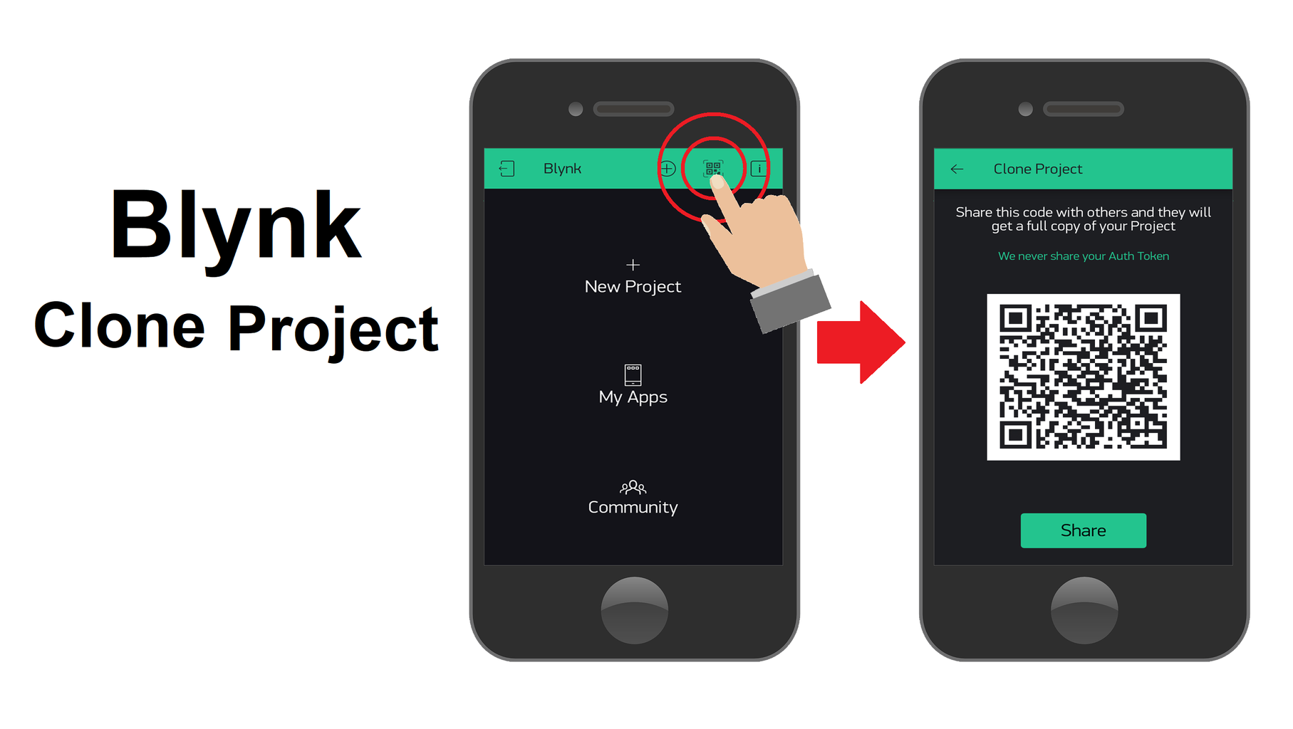
- "Clone" button - It creates a QR code that can share an exact copy of the project with another Blynk App account. This form of project sharing is secure, as long as only the QR code is shared and not the Auto Tokens.
Devices settings of project:
On this same project settings page, you will find the page dedicated to the various devices that the project controls. By selecting this tab, a page is displayed and it is possible to view, add and remove all the devices used in the project.
When a device is selected, a page will open where you can edit and confirm the following device settings (See image above):
- "Name" text box - It gives you the opportunity to check or change the name of the device so that it is easier to find.
- Device name: "Device#1";
- "Choose device" option - Allows you to check or change the type of device used for assembly.
- Type of equipment: "ESP8266";
- "Connection type" option - Allows you to check or change the type of connectivity that the selected device uses.
- Type of connectivity: "Wi-Fi";
Allows you to access or modify the "Auth Token" - If the device's Auth Token code is compromised, simply press the "Refresh" button and a new code will be generated. By pressing the "Email" button this new code is sent to the email associated with the Blynk App account.
A very useful option when adding many devices to the project is the "+ New Tags" option, because it allows you to group these devices in order to make the project easier to organize.
After all the project settings are completed, it is time to finally turn it into Play mode, but it will still be necessary to upload the code in the ESP8266 ESP-01 module to finally test the assembly.
If you want to copy this project directly, with all the settings and ready to use, just use the following procedure (See the image above):
- Press on the QR code symbol on the home page of the BlynkApp;
- Authorize the use of the camera by the application;
- Point the smartphone camera at the QR code;
- The project will be instantly copied to your smartphone;
Step 3: Code Explanation


As you remember, the ESP-01 module is installed on the USBAdapter module and ready to be programmed. Now let's connect the module to one of the computer's USB connections and open the Arduino IDE.
For the ESP-01 module to be controlled by Blynk App, you will need to upload a code with all Blynk App authentications and your Wi-Fi network credentials.
So each device has a standard code with all the libraries and functions necessary for it to work correctly. To make this standard code easy for each device type used, the BlynkApp website has a page that allows you to find and copy the standard code to the ESP8266ESP-01 module (See code below).
Blynk example browser:https://examples.blynk.cc/?board=ESP8266&shield=ESP8266%20WiFi&example=GettingStarted%2FBlynkBlink
//Activates communication between the Blynk App and Serial Monitor:
#define BLYNK_PRINT Serial

#include <ESP8266WiFi.h>	//Import a "ESP8266_Lib" library.
#include <BlynkSimpleESP8266.h>	//Import a "BlynkSimpleShieldEsp8266" library.

//Authentication of account in the Blynk App.
char auth[] = "YourAuthToken";	//Enter the device's auth token code.

//Enter the WiFi credentials.
char ssid[] = "YourNetworkName";//Name of the Wi-Fi network.
char pass[] = "YourPassword";	//Wi-Fi network password.
	//Note: Set password to "" for open Wi-Fi networks.

//Run the SETUP function only once after pressing Reset:
void setup() {
	//Starts Communication Serial:
	Serial.begin(9600);

	//Starts Wi-Fi communication:
	Blynk.begin(auth, ssid, pass);
}

//Run the LOOP function repeatedly.:
void loop() {
	//Starts communication with the Blynk App:
	Blynk.run();

	//Place the remaining code for your project.
}
This assembly, together with the project developed in the Blynk App, has the advantage of not requiring you to change or add more lines of code to the standard code.
As mentioned in the previous step, by selecting the digital pins on the widget button, this button will directly control these pins and there is no need to put these functionalities in the code, which is why this set is one of the simplest IoT systems.
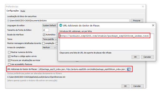
Now, to load the code for the ESP8266 ESP-01 module, you will need to configure the Arduino IDE (See image above). To configure, you must first install this module in the Arduino IDE and to do so we follow these steps:
- Open the "Preferences" page on the "File" tab;
- Copy the link below to the "Additional Plate Manager URL" link list on the "Preferences" page;
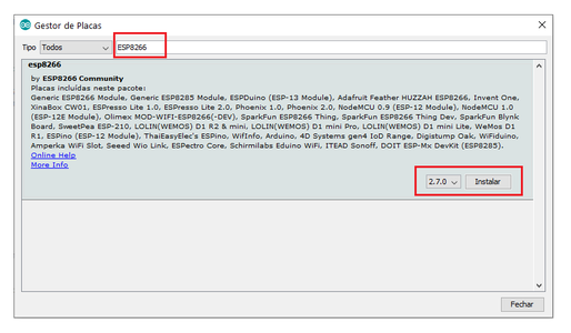
- Open the "Board Manager" page through the "Tools" tab of the " Boards" option;
- Search the ESP8266 module in the search bar;
- Press the "Install" button to install the ESP8266 module in the Arduino IDE;
After installing the board, you only need to select the model of the board used and its connection port, it can change depending on where the ESP-01 USB Adapter module is connected (See image above).
Now you can just upload the code for the ESP8266 ESP-01 module. When the uploading process is complete, the ESP-01 module is removed from the USB adapter and installed in the Relay module. After that, the "Reset" button must be pressed for Wi-Fi connectivity to start correctly.
Finally, the assembly is complete and ready. So, to test the mount just press the "Play" button found on the BlynkApp project construction page.
Next, you can check if the device is connected to the Blynk App, and if this is confirmed, the application automatically starts controlling the device, allowing you to turn the Table Lamp on and off through the Internet.
Thanks for watching our tutorials, the purpose of our channel is to contribute and help you in the development of projects, now also through modules for the IoT system. Don't miss the next tutorials and visit our channel on Youtube, Instagram, Facebook or Twitter.


Participated in the
Arduino Contest 2020


