

Introduction: Arduino Uno to Program ATTINY84 (Arduino V. 1.8.5)


More by the author:


About: Mech Eng
Using the Arduino Uno to program ATTINY84-20PU (Digikey item # ATTINY84-20-PU-ND).
This Instructable shows how to use the Arduino platform to work with physically smaller processors, such as the ATtiny84 (84/44/24). This example is specifically for the ATtiny84-20PU processor but can be adapted for the others boards by selecting the appropriate board from the Arduino software (i.e., Arduino IDE) and modifying the pinouts as required.
(Updated for Arduino 1.8.5)
Step 1: Add ATtiny Core Supprt to Arduino IDE Software
For Arduino 1.8.5:
- Open Arduino software (aka Arduino Integrated Development Environment [IDE]).
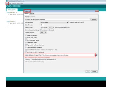
- Open preferences: [FILE] --> [PREFERENCES]
- Paste URL into Additional Boards Manager URLs: http://drazzy.com/package_drazzy.com_index.json
Step 2: Program Arduino for Use As an In-System Programmer (ISP)


- Select Arduino board: [TOOLS] --> [BOARD] -->[ARDUINO/GENUINO UNO] . Note: although I have the Arduino UNO I have replaced the processor with a pre-programmed Atmega328P that requires that I select "Arduino Duemilanove or Diecimila."
- Select Programmer: [TOOLS] --> [PROGRAMMER] -->[AVR ISP] .
- Open ArduinoISP sketch: [FILE] --> [EXAMPLES] --> [11.ArduinoISP] --> [ArduinoISP]
- Upload sketch.
Step 3: Connect ATtiny84 for Programming
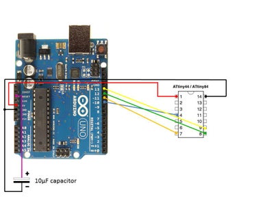

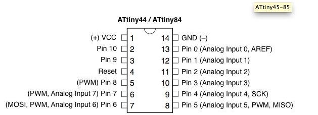
Connect the Arduino Pins to the ATtiny84 pins:
- Arduino 5V to ATtiny84 Pin 1
- Arduino Pin 10 to ATtiny84 Pin 4
- Arduino Pin 11 to ATTiny84 Pin 7
- Arduino Pin 12 to ATtiny84 Pin 8
- Arduino Pin 13 to ATtiny84 Pin 9
- Arduino GND to ATtiny84 Pin 14
- Arduino RESET to 10uF capacitor (+ side / long leg)
- GND to 10uF capacitor (- side / short leg)
Step 4: Set Arduino to Program ATtiny84

- Select Arduino board: [TOOLS] --> [BOARD]
-->[ATtiny24/44/84]. Now additional board options will appear in the Tools menu next time Tools is opened. - Select B.O.D. disabled: [TOOLS] --> [B.O.D.] -->[B.O.D. Disabled]
- Select LTO disabled: [TOOLS] --> [LTO 1.6.11+ only] -->[Disabled]
- Select Pin Mapping counterclockwise: [TOOLS] --> [Pin Mapping] -->[Counterclockwise]
- Select Chip Attiny84: [TOOLS] --> [Chip] -->[Attiny84]
- Select Clock 8MHz: [TOOLS] --> [Clock] -->[8 MHz internal]
- Burn bootloader: [TOOLS] --> [Burn Bootloader]
Step 5: Program ATtiny84

- Open Blink sketch: [FILE] --> [EXAMPLES] -->[01.Basics]-->[Blink]
- Edit sketch:
- Prior to void setup(), define pin name (led) and location (pin 0): int led =0;
- place “LED_BUILTIN” with “led” in void stetup() and in void loop()
- Upload sketch.
- Power off and disconnect from Arduino.
Step 6: Connect ATtiny84 to Run As Stand-Alone

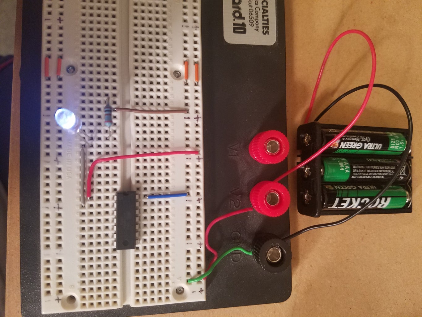
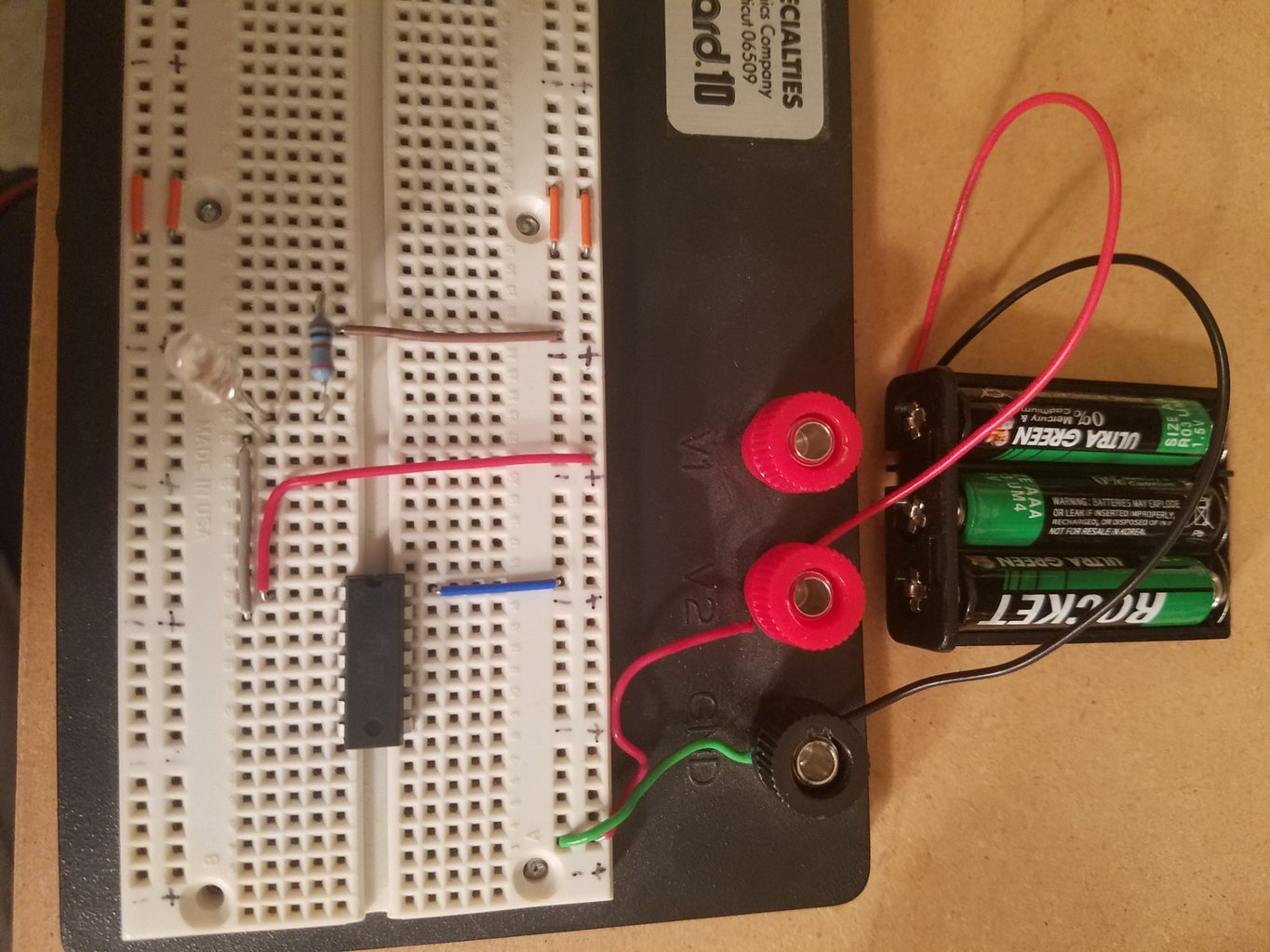
- ATtiny Pin 1 to 5V source (don't actually turn on power yet)
- ATtiny Pin 2 to LED (long leg)
- ATtiny Pin 14 to Ground
- LED (short leg) to Resistor (end 1) between 100 and 1k Ohm
- Resistor (end 2) to Ground
- Turn on power to ATtiny84


