

Introduction: Automatic Raspberry Pico W Watering System


This is how to build an automatic watering system using the Raspberry Pi Pico W.
The supplies I have listed are EXACTLY what I purchased in order to get this working.
Fair warning, this was a pain in the butt to get going but it finally works. I'm mostly putting this here so I can remember how to make this thing when I grow to be old and senile so it may seem dumbed down but that's because it's supposed to be.
Supplies

Step 1: Get Your Raspberry Pico W Ready

Use this link to get your Pico W ready to program. Follow every single step to the letter.
I did the dude thing which was to just skim through and free ball it and that landed me in a 30 minute mental debug loop.
Step 2: Get Your Pico on the Breadboard

Place it on the bread board exactly like this. This will help keep everything nice and neat. You can start soldering everything to pins and all but just for prototyping, stick with this.
Step 3: Physical Assembly


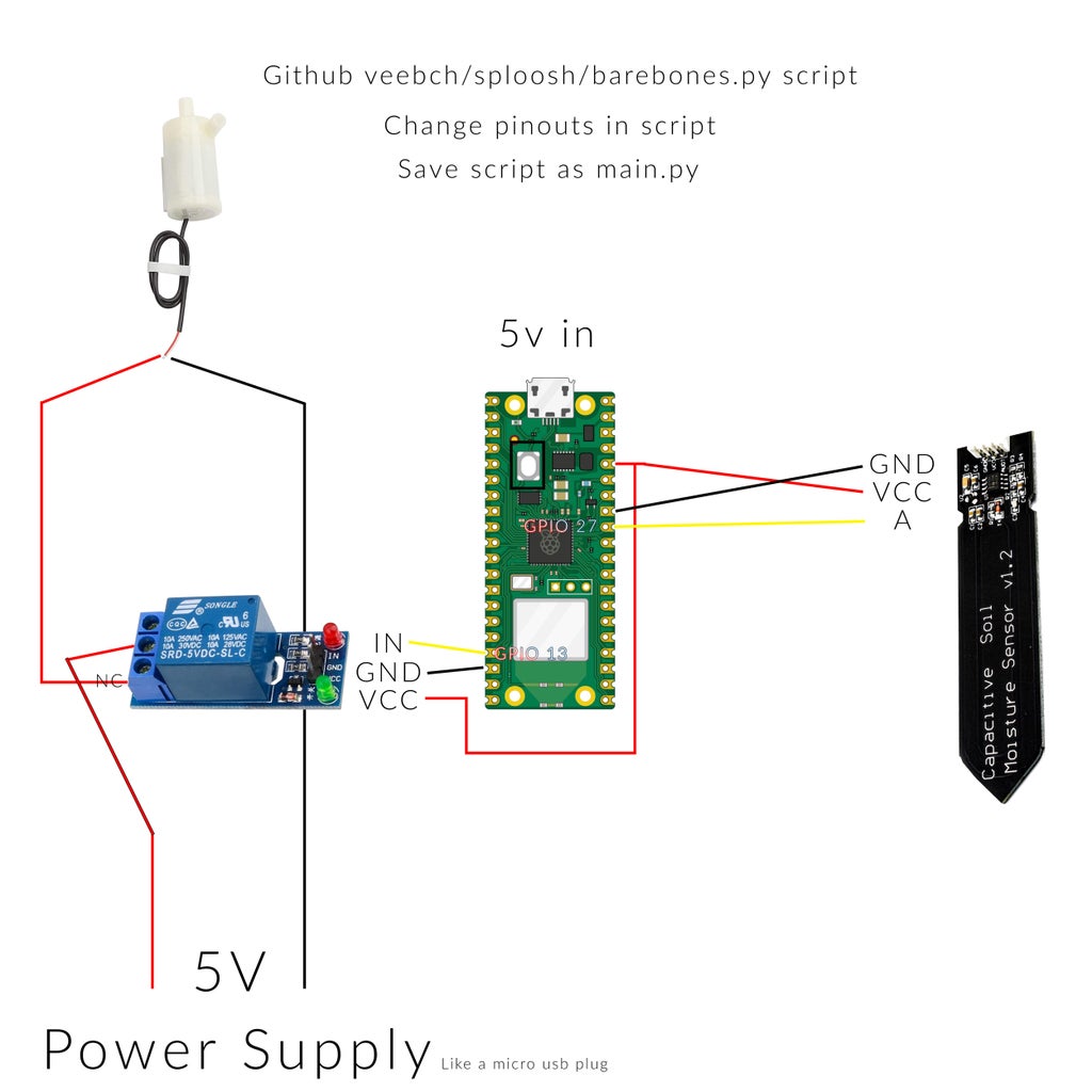
Setup your Pico like the diagram above. It's kinda jank but its the best I had. PLEASE USE THE PICO W DIAGRAM ABOVE TO PIN EVERYTHING OUT.
This was a pain in my side for a hot minute so just use the diagram above to be sure your connections are in the right place. Better yet, get a breakout board like this one and plug everything in that way. I never saw that until writing this. The more ya know, right?
(For whatever reason Instructibles is super duper compressing the image so I added it in the supporting files below)
Step 4: Code

Use this link to get to the code. Paste this code into Thonny. Don't run anything yet.
Step 5: CHANGE THE PINOUTS

Aight so this part is super crucial and specific to the Pico W so PLEASE pay attention. If you don't have a Pico W you can leave this pretty much the same.
- Change the led to the onboard LED:
led=Pin(25,Pin.OUT)
to
led=Pin("LED",Pin.OUT)
- Change the relay pin and wetness pinouts:
relaypin = Pin(15, mode = Pin.OUT)
wetness = machine.ADC(26)
to
relaypin = Pin(TheLocationOfYourRelayINWire, mode = Pin.OUT)
wetness = machine.ADC(TheLocationOfYourMoistureSensorAUOTWire)
Please note that "TheLocationOfYourRelayWire" and "TheLocationOfYourMoistureSensorAUOTWire" should
be numbers. Don't literally copy that in. So in my case it will look like this:
relaypin = Pin(13, mode = Pin.OUT)
wetness = machine.ADC(27)
Again, use the above pinout sheet to locate where your pins are. When you are specifying which pin is what in the code, its in reference to the GPIO pin location, not the actual physical location of the pin itself.
To clarify, on that diagram the physical Pin 17 is the GPIO13 pin, just as physical pin 31 is the GPIO26 pin. .
(Why am I touching on this? BC I'm dumb and didn't get that at first. Learn through me, el dumbo.)
- Change the relay pin further down
relaypin = Pin(15, mode = Pin.OUT, value =0 )
to
relaypin = Pin(TheLocationOfYourRelayWire, mode = Pin.OUT, value =0 )
If you wanna take the risk you can just download the code here, I've attached the script I used down below.

Step 6: Test
Alrighty, everything should be in place so time to give this thing a shot. These little pumps aren't gonna die on you too fast if you run them dry so you don't need to place em in water or anything just yet.
- Plug your Pico in and start the code.
- plug in your 5v Power supply to the pump.
- If your moisture sensor is out of water it should turn on the relay thus activating the pump.
- If it doesn't check to ensure your positive lead from your pump is plugged into the Normally closed (NC) terminal of your relay
- If that doesn't work try changing the calibratewet and calibratedry variables.
- If your moisture sensor is in water it should stop the pump
- Monitor the readings from the Shell and see your final product shine!
Step 7: Finish!
Like I said, this is super down and dirty. I'll try and update with a finished version of my own, but I want to make some improvements such as:
- Waterproofing the whole thing
- Using heat shrink tubing for the solder joints
- Use a breakout board instead of a bread board, or just solder directly to a pinless Pico.
- Add LED's to the final design to show off/on states
- Perhaps integrate a wireless design or UI
Anyways, I hope this was slightly helpful for ya. If you run into any issues please let me know down below.


