

Introduction: Basic (PWM) Motor Speed Control Using 555 Timer ICs


This is the first part of supposed to be a two-part instructable about speed control of a DC motor using 555 timer ICs meant to cater those who are still starting to make electronics a hobby and beginners like me in a way. In this part, I will talk about the basics of motor speed control specifically via Pulse Width Modulation controlled by an input voltage signal(using a potentiometer). In the second part, I will try to replace the input voltage signal with let's say, a temperature sensor to vary the pulse width of the voltage signal fed to a DC motor.
This is my first time making projects related to the 555 timer IC. Therefore, all the concepts that I would tackle later on are heavily based on books, web sites, and the Datasheet provided by the manufacturer. Do note that this is just a project demo and most likely may not be suitable for serious applications. There are also a lot of previously published instructables or other tutorials found in the web about this topic which uses only one 555 timer IC but i don't really have a full understanding as to how it exactly works as of now so im stuck with using two. :-(
If you are a beginner like me, links are provided at the end of steps 1,2 and 3 as you go along. Please check all the links and read if you want to dig deeper into the topic discussed per step as I would only talk about the essential concepts needed for this project. Im still no expert in this field so the knowledge that i may impart would be the very basic concepts that I can fully understand at my current level. So if you have corrections, please use the comments section to inform me right away so that I can learn from you.
For those who have available microcontrollers at hand (say an arduino), you may just skip this instructable and refer to this site:
http://www.dummies.com/how-to/content/how-to-contr...
for a more sophisticated way of controlling DC motor speeds with less wiring steps, less components, less effort... with just little programming skills required and basic understanding of the code. Other microcontroller boards have their own site for such tutorials so Google is the answer. I actually have an arduino board available but it seems that I would learn a lot about this topic if I would try to implement it the hard way.
For some personal questions, concerns, clarifications, corrections etc., you can just email me at: mttarvina@up.edu.ph
*******************************************************************************
To start, here are some key points that would serve as the overview of this demonstration:
- Applies the BASIC circuit configuration of both Astable and Monostable modes of the 555 timer IC in one project
- Output voltage signal across DC motor = square wave at 10Hz frequency with peak voltage at around 7.5 - 8 Volts
- Output frequency is constant at 10Hz with varying pulse width from 12% to 95% duty cycle
- Uses two 555 timer ICs to serve as (1) clock input and (2) as pulse width modulator both running at 10Hz frequency
- Uses a DC motor with a rated voltage of 9V at rated speed of 2400rpm (NO LOAD - to minimize current consumption)
- A 10Hz working frequency is chosen so that the output will be noticeable to the naked eye when the motor is replaced by an LED(since i initially wanted to see how it affects the blinking behavior of the LED based on how long it lights up versus how long it turns off).
Step 1: A Quick Look at DC Motors and Speed Control

A DC motor is a device that converts electrical energy into a rotational mechanical energy. It is a two lead device that has a rotary shaft rotating by means of electromagnetic induction with rotational speeds dependent on the supplied current or voltage. Generally, motors are low resistance devices(about 5 to 20ohms) when you measure the resistance between its two leads. This is due to the fact that the internal structure of a motor consists of coils of magnet wire with up to thousands of windings just like a complex electomagnet. So you might think that supplying it with lets say a 9V source would result to a very high current passing through the motor. This is not the case however since they are not passive devices like a resistor and a simple ohm's does not apply. If you want to to know the exact relation between voltage, current and speed in a motor, you might want to check the references below for further reading especially if you want to know the specific parts as well and a simple demonstration of its operation.
Motors in a practical sense
You can think of it this way: You have a two terminal device that rotates in response to the applied DC voltage or DC current. Now how exactly is rotational motion dependent on voltage and current? Practically, an increase in voltage or current supplied would result to an increase in rotational speed in terms of revoltions per minute. We can say that at 0 volt or 0 ampere, the motor would cease to rotate and increasing the amount of voltage or current bit by bit would gradually increase the rotational speed of the motor. But always remember that practical devices have limitations and you can not obviously increase the applied voltage/current up to infinity to have a very very large unimaginable rotational speed(remember the speed of light?)
If you opt to buy a DC motor, you might be asked for a voltage rating. And in some cases, you can read from the label some parameters such as voltage rating and speed rating. What I learned from one of my electronics class is that if you are given a voltage and speed rating, that only means that the motor would rotate at that rated speed if you supply it with a voltage equal to its rated voltage. Knowing its rated voltage would also tell you something about the range of voltages that you are allowed to supply in order not to damage the motor. The rated voltage also tells you at what voltage the motor runs most efficiently as stated by Paul Scherz in his book[1]. You can supply the motor with a voltage less than its rated voltage and the motor would just rotate more slowly. If you have a DC motor rated at 9V, you can supply it with a 1V DC source or battery and in some cases the motor would rotate very slowly while in some cases, it would cease to rotate. If you have DC motor at hand, you can check if what is the minimum supply voltage needed to cause rotation. Supplying a voltage greater than the rated voltage is where you have to be careful. At this point the motor might start to heat up as you increase the supply further and continuing further ahead will result to a doomsday apocalypse.
The No load and loaded scenario
Basically when we talk about a DC motor with load, that's the time when we are actually putting it to good use. But enough of those simple words. It means that the motor is now the one causing the loaded mechanism to function. You may use it for your remote controlled cars, in a generator, an electric fan (when you attach the fan blades) etc. The main implication of connecting a load to the motor is that, it hinders the rotation of the motor shaft mainly because it is an added weight and an additional torque is required to rotate it. It creates friction in some sense that slows down the rotation. The motor then tends to maintain the rotational speed it originally had at no load condition. To achieve this, it draws current that is about a hundred or even a thousand times its initial no load current for a given constant supply voltage. In this project, the motor is at no load condition since we are only looking at the speed parameter in response to a PWM signal. Also, we would like to minimize power consumption when testing the circuit later on.
Methods of speed control
To control the speed of the motor, we have to control certain electrical parameters that directly affect its speed. Obviously, we have to adjust the voltage and current supplied to it.
One way is that at constant supply voltage, you might want to put a variable resistor(potentiometer) in series with the motor to adjust/limit the current that it draws during operation. The bad thing about this method is that by limiting the current flow changes the value of the series resistor which also changes the voltage across the motor. When the motor is loaded, it draws a significantly large amount of current thus increasing the power across the series resistor. The power across the resistor will just be converted into wasted heat.
Another way is to use a Common emitter bjt transistor configuration with the motor as the load to adjust the current through the motor by changing the supply voltage at the base-emitter junction of the transitor. However, this is harder to predict since the realtionship between the Vbe and Ic of the transistor is exponential. Aside from additional transistor concepts that you have to keep in mind, the transistor itself dissipates additional power as heat.
Another alternative and probably the most popular among speed control methods is the pulse width modulation. This method generates a pulse signal of voltage or current switching from on(HIGH) and off(LOW) with definite intervals on each state and a defined constant frequency overall. Note that this kind of voltage signal would still look like a constant DC voltage as seen by the motor. If you supply a DC motor with a 9V source and a switch but you constantly press the switch between On and Off reduces the average voltage supply as seen by the motor thus reducing its speed.
For a more detailed discussion on PWM, we now proceed to the next step.
References:
[1] Chapter 13, Practical Electronics for Inventors by Paul Scherz (2000)
[2] Chapter 22, Encyclopedia of Electronic Components Vol.1 by Charles Platt (2013)
Step 2: More on Pulse Width Modulation

PWM or pulse width modulation applies to square wave signals of voltages and current. In a square wave voltage signal, there are only two values for the voltage level: the HIGH(Vcc) and LOW(ground - 0). Square wave signals are periodic and has a constant frequency of operation.
Duty Cycle and Pulse Width
Unlike a pure DC signal, the square wave signal has a definite interval in which the voltage/current state is HIGH and another definite interval in which the voltage/current state is LOW. The sum of these two intervals make up the period of the square wave. Duty cycle is then defined as the ratio of the time duration where the signal is at state HIGH divided by the total time it takes to reach one period. The term "pulse width" is the amount of time the state of the signal is HIGH. Most of the time, duty cycle or pulse width alone can fully describe a square wave provided that the frequency or the period of the square wave signal is defined.
Example: A 50% duty cycle means that one period of a 1 Hz signal consists of a pulse width(signal HIGH state) equal to 0.5seconds and a signal LOW state equal to 0.5seconds. A 90% duty cycle of the same signal frequency consists of a pulse width(signal HIGH state) equal to 0.9 seconds and a signal LOW state equal to 0.1 second.
Since square waves are periodic, it has an equivalent DC value or average value for a given period and the value is solved through integration(please refer to the image above). The DC value of a square signal is always less than or equal to the peak value where the signal is HIGH. Duty cycle can also be solved using the average value and the peak value of the signal HIGH state.
duty cycle = [ dc value / peak value ] x 100%
Example: A 50% duty cycle of a 1 Hz square wave signal(HIGH = 5V, LOW = 0V) is equal to a 2.5V dc voltage signal
Now based on this basic concepts, what happens if we vary the pulse width of a square wave signal with frequency held constant?
Scenario: Let's say we have a 1 Hz square wave signal(HIGH = 5V, LOW = 0V) and we want to compare the equivalent dc values of a 10%, 50% and a 90% duty cycle. For a 10% duty cycle, we will have an equivalent dc value of 0.5V. For a 50% duty cycle, the dc value is equivalent to 2.5V and for a 90% duty cycle, the dc value is equivalent to 4.5V.
Conclusion
Duty cycle is linearly proportional to the equivalent DC value of a square wave signal. Applying this signal to a motor and then varying the duty cycle/pulse width would also vary the equivalent dc value as seen by the motor thus varying its rotational speed.
References:
[1] https://learn.sparkfun.com/tutorials/pulse-width-...
[2] http://www.allaboutcircuits.com/textbook/semicond...
[3] http://www.embedded.com/electronics-blogs/beginne...
Step 3: The 555 Timer IC and Its Modes of Operation


The 555 timer IC is a monolithic timing circuit that produces accurate timing delays and oscillations in a form of a square wave signal. This small IC has a lot of applications such as in oscillators, tachometers, waveform generators, control systems etc.
Some features of 555 timer ICs are:
-It operates from a wide range of power supplies ranging from + 5 Volts to + 18 Volts supply voltage.
-Sinking or sourcing 200 mA of load current.
-The external components should be selected properly so that the timing intervals can be made into several minutes along with the frequencies exceeding several hundred kilo hertz.
-The output of a 555 timer can drive a transistor-transistor logic (TTL) due to its high current output.
-It has a temperature stability of 50 parts per million (ppm) per degree Celsius change in temperature, or equivalently 0.005 %/ °C.
-The duty cycle of the timer is adjustable.
In this step, I will not talk about how the internal structure really works(just refer to the links below especially the datasheets). You can just think of it as a black box with 8 pins and with the help of external components like resistors and capacitors, one can produce oscillations or timing delays dependent on the values of the externally connected components.
Now lets talk about the two modes of operation of the 555 timer and its basic circuit configuration based on the datasheet.
Monostable Mode:
For a monostable mode, the timer creates a timing delay by switching its output to HIGH for the whole duration of the delay. This delay is triggered by an external input to Pin 2 of the IC. When the input Pin goes LOW, the timing delay starts. The duration of the delay is dependent on the values of the external resistor and capacitor and is calculated using the formula:
tdelay = 1.1RC
If the input signal is periodic, then the output is also periodic with the same frequency. If the input signal goes LOW for every 1 second, then the ouput timing delay is retriggered every 1 second.
Suppose that the input LOW lasts for 1second but your timing delay lasts only for 0.5seconds. At time t=0, let's say that the input starts switching LOW and the output starts switching HIGH and after a timing delay of 0.5 second, the output should switch to LOW to signal the end of the delay. At this point however (t = 0.5), the input is still at LOW state. This may cause the output to instantly switch again to HIGH retriggering the delay and this scenario should be avoided by setting the LOW duration of the input to a relatively smaller value as compared to your timing delay duration. In other words, one can increase the duty cycle of the input to decrease the time duration of its LOW state(increase the time it is at state HIGH).
Astable mode:
The astable mode functions just like an oscillator which outputs a square wave with frequency, pulse width and duty cycle dependent on the values of the external resistors and the capacitor. This oscillation shall go on forever unless... if you cut the power supply of course. The pulse width, duty cycle and the frequency can be calculated as follows:
pulse width(t high) = 0.693(Ra + Rb)C
t low = 0.693(Rb)C
period = 0.693(Ra + 2Rb)C
frequency = 1 / period
duty cycle = [t high / period] x 100%
Given this formulas, we can see that changing the value of just one component would result to a different set of values for the pulse width, frequency and duty cycle of the signal. Not only we are varying the pulse width but the frequency as well by varying the value of Rb or Ra.
The basic circuit configuration of both the monostable and astable mode is shown in the images above taken from the datasheet of the NE555(Texas Instruments)
References:
[1] Chapter 6, Practical Electronics Handbook 6th Ed. by Ian Sinclair and John Dunton
[2] LM555 datasheet: http://www.ti.com/lit/ds/symlink/lm555.pdf
[3] NE555 datasheet: http://www.ti.com/lit/ds/symlink/ne555.pdf
[4] http://www.555-timer-circuits.com/
[5] http://www.electronics-tutorials.ws/waveforms/555...
Step 4: Design Motivation


As said earlier, one of the efficient ways to control the speed of the motor is through pulse width modulation. If we plan to use the basic configuration of the astable mode of the 555 timer, it will not be suitable since varying the pulse width also varies the frequency of the square wave signal.
The motivation for this project is the one provided in the datasheet of the NE555 timer. In figure 18 of the datasheet, a diagram is provided for a pulse width modulation circuit. This uses a 555 timer in monostable mode with two inputs. One is for the clock input(pin 2) which is responsible for the trigerring of the output time delay signal. Another one is the modulating input(pin 5) which alters the threshold voltage within the timer and in turn alters the output time delay independent of the values of the external resistor and capacitor. When i say independent, what i mean is that the timing delay does not follow the formula discussed in step 3 for a monostable operation.
Looking at the diagram i instantly thought of using another 555 timer IC to act as the clock input and will be configured to operate in astable mode with about 90% duty cycle output to minimize the duration of state LOW. And for the modulating input, I can just put a potentiometer sourced from Vcc to vary the input voltage from 0V to Vcc.
References:
[1] NE555 datasheet: http://www.ti.com/lit/ds/symlink/ne555.pdf
Step 5: Pre-design Calculations and Design Implementation

The design is pretty simple. We have two stages: first is the clock stage that generates an oscillation with constant frequency and duty cycle, the second stage creates a variable timing delay in response to a trigger input and a control voltage with a frequency the same as the input frequency.
A 10Hz working frequency is chosen since I initially thought of using an LED to observe how it blinks when connected at the output and later on will be replaced by a DC motor. Generally, this is a very low working frequency when dealing with motors since you may notice some jerking when operating at low duty cycles. Usually when dealing with motors, a higher frequency is required(100Hz or more) for a smooth operation of the motor and that the obvious switching between on and off state would hardly be noticeable. In my case however, it seems that the motor still runs smoothly at 10Hz.
For the first stage, we are using a 555 timer in astable mode operating at 10Hz frequency and 90% duty cycle. To achieve this, we have to calculate specific values for the resistors Ra, Rb and the capacitor C. In this case, i chose a capacitor value of 4.7uF and from this value, it was found out that Ra = 24Kohm and Rb = 3Kohm(refer to one of the images above). For Ra, it is better to use a 20kohm resistor and a 5kohm potentiometer to fine tune the frequency during actual circuit implementation.
For the second stage, the diagram for a pulse width modulation circuit provided by the datasheet says that we have to choose values for R and C such that RC = 0.25 x clock input period. Given a capacitor value of 10uF,, R should be equal to 2.5Kohm but I didn't have a 2.5kohm available so I decided to replace it with a 3kohm one knowing that the timing delay later on would be dependent on the control voltage.
For the control voltage, I chose a 50kohm potentiometer with the two outside terminals connected to Vcc and ground while the middle terminal connected to the control voltage pin(pin 5) of the second 555 timer IC.
Step 6: Circuit Implementation
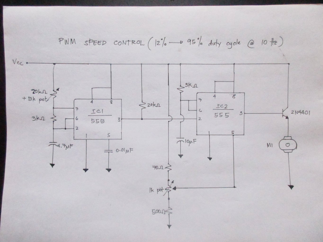


I came up with a circuit diagram as shown above. You can configure this on a breadboard. You may put an additional flyback diode in parallel with the motor to protect the circuit from sudden voltage spikes. You may also notice a series of resistors connected to the control voltage pin of IC2 (the 70ohm, 500ohm and a 1kohm potentiometer). Again you may replace this configuration with a single 50kohm potentiometer or even a larger value potentiometer. This is essential for the next step since the circuit diagram presented above is already the final circuit diagram. We need to test the output first in response to an input control voltage to see if it truly adheres to our initial assumptions.
Materials:
-two LM555 timer ICs
-two 20kohm resistor
-5kohm, 1kohm, and 50kohm potentiometer
-two 3kohm resistor
-70ohm resistor
-500ohm resistor
-4.7uF 16V cap
-10uF 16V cap
-0.01uF cap
-9V DC motor
-2N4401 NPN transistor
-constant 9V source
-diode(optional for motor)
Step 7: The Control Voltage

To test how the output responds to the control voltage, I decided to inially use a 50kohm potentiometer to vary the input voltage to pin 5 of IC2. I found out that when the input voltage is below 2.9V, the output frequency is unpredictable anymore and sometimes my multimeter reads 15Hz, 20Hz, 30Hz etc. Also at 2.9V, the multimeter reads an output duty cycle of around 11% percent. If you still remember the scenario that we've discussed previosly in Step 3(Monostable operation of 555 timere IC), that is exactly the scenario that is happening when the input control voltage is decreased further from 2.9 V. Ideally the output duty cycle should decrease but remember that the clock duty cycle is at 90% therefore, the duration of the input LOW state is 1 tenth of the total period. Decreasing the output duty cycle also means decreasing the time delay duration and when it reaches a point where the output time delay is less than the input LOW duration of the clock, the output retriggers since when it switches to HIGH, the input trigger is still LOW resetting the delay thus as if the frequency is increased as seen by the multimeter. Given these conditions, the ideal minimum duty cycle output must be 10% but based on initial measurements, it was found out to be around 11-12%.
On the other hand, when the input control voltage is greater than 8.6V at 95% measured duty cycle, the output frequency is reduced to 5Hz and the only explanation that I can think of is the following: increasing the duty cycle further means increasing the time delay duration where it overlaps the next trigger input. When the input triggers LOW, the output is still HIGH which means that the time delay is still up so the trigger input is ignored. Its as if IC2 skips one input trigger at a time thus reducing the output frequency by half.
Based on this findings, we need to create a resistor configuration, this time using a 1kohm potentiometer, such that the minimum voltage input to the control pin of IC2 would be 2.9V and the maximum voltage input would be 8.6V from a voltage supply of 9V. To achieve this, I found out that I need two additional resistors in series with the potentiometer. (Calculations are shown in the image above).
Having this resistor configuration, we are now ready to test if the whole circuit works as initally planned.
Step 8: Testing the Actual Circuit/Results and Discussion


The last and final step would be to test some needed parameters to validate out initial assumptions. I didn't have a speed measuring device available but luckily my multimeter have additional functions for frequency and duty cycle measurements. I have no choice but to believe in him(the multimeter) since he's the only one i've got. The speed of the motor can be observed by listening the kind of sound it generates when rotating and can be verified by measuring the duty cycle and the equivalent DC voltage across it. The results are tabulated as shown in the images. One can also verify the data by watching this video clip I recorded when testing the circuit:
https://drive.google.com/file/d/0B4XH_hIUHi0-VFRPb...
Once again, this project is meant for beginners who want to look for an actual demonstration of how to make use of PWM and how to generated PWM signals using the basic configuration of operating modes of the 555 timer IC.
A big thanks if you reached this step. Hopefully I can upload the Part 2 of this project soon.


