

Introduction: Battery Saver, Discharge Protector Cut-out Switch With ATtiny85 for Lead Acid Car or Lipo Battery


As I need several battery protectors for my cars and solar systems I had found the commercial ones at $49 too expensive. They also use too much power with 6 mA. I could not find any instructions on the subject. So I made my own that draws 2mA.
This instructable is outdated and I have developed another more simpler buttery cut off switch. I keep it online due to popular demand.
FIND THE NEW DESIGN HERE:
https://www.instructables.com/id/Battery-Cut-Out-S...
DISCLAIMER
I Robert Moller assume no responsibility or liability for any errors or omissions in the content of this Instructable. The information contained in this site is provided on an “as is” basis with no guarantees of completeness, accuracy, usefulness or timeliness. The information in this site is intended solely for the personal non-commercial use of the user who accepts full responsibility for its use. While I have taken every precaution to insure that the content of this Instructable is both current and accurate, errors can occur.
Learn all about BATTERIES and understand how they work.
Smart Microcontroller Battery Discharge Protector.
Protects your 12Volt lead acid car battery from total discharge by switching off appliances such as fridges and TV sets before the battery voltage drops to an unrecoverable level.
Automatically cuts power supply when the battery voltage is below the programmed setting. Maximum Voltage 35V Maximum working current 20A. A LED will blink just before power cuts out to indicate battery status. If the battery reaches pre-set level, power is automatically restored.
FEATURES Prevents battery discharge Protects your battery against excessive discharge when using accessories connected to it. Lights drain the battery and destroy your battery. Most fridges turn off automatically to protect the fridge motor but not your battery. Designed to turn off accessories before they discharge the battery to low. Once turned off they remain inoperable until the battery reaches your set voltage above 12.8 volts again.
In the software, you can change the voltage settings and are able to fine tune your battery protection based on load and demand. This device will protect your expensive batteries from damage due to over discharging them.
- Programmed to switch off at 12 volts.
- Blinks a warning LED before switching off. Indicating the power is low.
- Completely switches off any drain ( except for the Tiny that keeps monitoring the status)
Other features of this ingenious Masterduino MK1 board are that it has a small ATtiny 85 chip microcontroller. But the outcome is very powerful due to the mosfets that switch your power on and off. There are two things that can be switched on and off or have a PWM output. Pulse Width Modulation. Or dimming, flickering lights on and off.
This board can protect your battery from discharging shortening battery life.
There are two extra inputs A3 and A2 that can be used to attach sensors for other projects to build.
Or should I call it MASTERDUINO as many other things can be made with this board?
- Gardening, Watering, overflow sensing, moisture sensing, sprinklers
- Water pumps, hydroponic timers, water level, overflow
- Lighting, flickering lights, dimming, PIR sensing
- Panning x and y axes · DC motor, stepper motor, servo motor
- Timers ( a switching spark will turn the device briefly on before it settles)
- Solar
A few of those will be covered in my next Instructables.
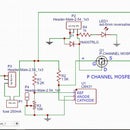
The two NTD5867N Mosfet’s are small in size but very powerful and can handle 60 volts and 20A. Just see them as a relay that switches the negative power rail. The resistors near the Mosfet are to make sure they completely turn off. Motors can also be attached to those. (use a diode)
Be aware that this Mosfet switches negative (ground) and not the plus rail.
For more info on N Drive and the Mosfet: http://www.freetronics.com.au/pages/ndrive-quicks...
In those instructions, a diode is used for the motor. With a diode, the motor runs only in one direction. If you need to reverse the motor use a motor shield and a 100nF capacitor instead.
The DC-DC converter on the board handles only up to 35 Volts for a short time and 28 volts for longer periods. Any higher voltage must go around the circuit and not be connected thru the circuit.
Specifications
Model: Battery Protector Cut Out MK1 Output Power 20A Input voltage: 6 to 28V Reverse polarity protected Auto reset short circuit fuse to protect the ATtiny 85 chip Screw terminals Size 7.5cm x 4cm
Parts list
4 terminal blocks
8 pin socket
1 ATtiny 85 chip pre-programmed ( cutting the power at 12.2 volts)
1 dc to dc converter to power the Tiny (eBay) https://www.ebay.com.au/itm/New-Mini-5V-3A-Step-Do...
1 resettable fuse 250mAH2 NTD5867N Mosfet’s (Element 14)
1 Diode N4004 (reverse polarity protection)
2x 1K resistors 3x 10K resistors 1x 18K resistor
voltage divider resistors for 12-volt system
1x18K to battery and 1x10K to ground
8 male headers
More information on voltage dividers to calculate a different voltage.
I use a 12 volt Battery the highest voltage when it is charging so that the outcome going into the input A1 of the Tiny is 5 volts. The maximum the Tiny input can handle is 5.5 to 6 volts. If you follow this link you do not need to be a mathematician and just work with the calculator provided.
https://learn.sparkfun.com/tutorials/voltage-divi...
Car Batteries If used in a dual battery system protecting the load battery the settings can be lowered to 11.89 volts. If you discharge a lead acid battery lower than 11.89 volts you damage it.
Battery 4.2 Volt |----o------/\/\/\-----o----/\/\/\----=-o----|Battery negative
More info in the code.
Step 1: Learn About Batteries

LEARN ABOUT BATTERIES
A car battery is fully charged at 12.66 volts, charges at around 13.9 to 14.7 volts. This battery protector does not charge but can stay connected while charging. It protects the battery from discharging too low and prevents battery damage.
The battery monitor can be used on the main starter battery and can be programmed to cut out the power at 12.2 or 12.3 volts to have enough cranking power to start the car. Experiment with it.
*below data if you use a 12 Volt Battery
*AGM 12 Volt battery in a Car dual system or other.
*Healthy resting voltage 12.8V-13V
*Absorption Voltage 14.7V (charging)
*Float Voltage 13.8
*Deat flat 11.89
12.66v . . . . . . . . . .100%
12.45v . . . . . . . . . . 75%
12.24v . . . . . . . . . . 50%
12.06v . . . . . . . . . . 25%
11.89v . . . . . . . . . . 0%
Lipo Battery Each cell has 3.7 volts, charged at 4.2 volts and discharged at 3.2 volts.
If you discharge the battery lower than that it can explode, start a fire or get permanently damaged.
Please note that Lipo batteries should not be left unattended when charging. Those can set off a fire from overcharging, excessive heat and cannot be put out with water.
I was informed that they keep burning under water as they produce their own oxygen.
However, this instructable is to encourage you to build your own battery monitor and not scare you. But those warnings must be mentioned. I would suggest using it outside on a solar system or in your car.
Car batteries let off toxic explosive fumes. Those are not charged inside a house or car.
A dual battery is a second battery usually used in four wheels drives and campers.
If a battery does not fit inside the engine room as in my Toyota Prado you have to get a sealed battery inside the car. And usually a Deep cycle battery. Those are different from starter batteries and can handle lots of charging and discharging better. Most popular are AGM (Absorbed Glass Mat) batteries.
*lipo battery, (each cell )charging at 4.2, float at 3.7, half way at 3.45, flat at 3.2 volts
Step 2: CONSTRUCTION


Cables
When using higher power to a car fridge thicker wire must be used. My Engel Fridge draws 2.6 Amp. Depending on the cable length the size can be calculated here
http://www.rpc.com.au/pdf/Wire_Chart.pdf
Sample
At 13.85 volts dc with a 2.6 Amp fridge and a cable length of 2 meters, you will need a 0.59mm cable.
Any less and the cable gets hot, glows like a hot wire cutter or burns.
To think and you lose power as DC power does not like travel to far.
Or 12 volt 2.6 Amps, 2 meter= 0.38064 mm wire.
My fridge as a cable from the manufacturer that says 2x 1.3mm (16AWG) to be on the safe side.
I made Fritzing diagram to show you how to connect things.
Schematic for Eagle cat.
Assembly Guide
If you make your own or buy a circuit board of me or even a kit.
Solder the input terminal
Solder the diode
Solder the fuse
Solder the DC-Dc converter Solder the 8 pin socket
THEN APPLY POWER TO THE CIRCUIT AND ADJUST THE OUTPUT TO 5 VOLTS
Then disconnect power.
Solder the Mosfet’s and the 2x 1 K resistors and the 2x 10K resistors
Then insert the ATtiny chip the right way around. ( They have a little dot on one side)
On my board, there are different hole sizes provided at the output to directly connect 2 different outputs without using the blue terminals. The A2 and A3 input terminal are optional to use with other sensors Now we have R1 and R2 left over. Those two are voltage dividers and must be calculated for the Voltage you are putting into the circuit.
Samples input to A1
Input voltage 5Volt R1 and R2 0 =5V
Input voltage 9 volt R1=8K and R2 =10K volt out 5v
Input voltage 12 volt R1=15K and R2 = 10K out 4.8v
Input voltage 14 volt R1=18K and R2 = 10K out 5v
Input voltage 24 volt R1=27K and R2 = 7.5K out 5.22 v
Input voltage of LIPO 4.2 volt can go direct to A1 without a voltage divider as it is under 5volts
Installation Guide
- Connect a suitable red cable from the battery to the device (fridge, lamp) directly to the device and also to the battery protector.
- Connect a black cable to the cut out switch.
- Connect a black cable from the cut out to the device (fridge, lamp)
The battery protector switches the negative rail.
Attachments

Step 3: Code

Of course, you are keen to know how this works and change and upload your own code.
As there a plenty of tutorials, I will not bore pros with this part.
But for the newcomers, I have built and constructed a shield that makes it easy to program.
How to program the Tiny with Arduino UNO is now in my new Instructable.
And even have constructed a shield for this purpose.
https://www.instructables.com/id/Programming-ATtinys-Micro-Controllers-With-Arduino/
The code
I assume you now ask: How did you do the conversion;
If I want to cut the voltage at 12.3 volts I have to put in the code the value of 4.36 in the code.
It took me weeks of learning and trial and error. I just made up an XL Spreadsheet and worked it out.
Best is to get a variable power supply and adjust the voltage to where you like the circuit to cut the power.
Then measure at the A1 pin what voltage goes in. That is the number (the voltage) you are looking for.
=(D41/C42)*C48 in the XL sheet
Formula (5/14.1)*12.3 =4.36 if I want it to cut out at 12.3 volt
When the battery is charging at 14.1 volts, that becomes the highest charging voltage and should read with the right voltage divider resistors a value of 5 volts at the input A1 of the Tiny.
Step 4: Testing


Now the fun begins.
Do not forget to adjust the voltage on the DC-DC converter before you insert the chip.
I used a $19 Masters battery for my demo and later to be used in a mini solar system.
Take a multimeter with you when you buy one.
Be aware that if a lead acid battery sits there without charge for more than three months in the shop the sulfide will destroy the battery.
Now you know if the battery reads under 11.89 volt it is dead. Check the next one.
That is why you get a good trickle charger and keep it connected all the time or follow my next Instructables on how to connect this to a solar charger.
In my photos, you see that at 12.8 volts the Mosfet switches the light on. I used a LED with a 680 Ohms resistor to demonstrate.
At 12.3 the second Mosfet blinks on and off. The best part is that you may have the knowledge to change the code and use the second Mosfet to switch the first set of lights off.
Then with the power getting too low ....everything switches off. Except for the Tiny that keeps monitoring and will turn everything on again when the power is restored.
Adding a longer delay in the code can reduce the power consumption of the circuit.No LEDs that consume power are on the board on purpose. The circuit itself only consumes 2 mA with the LED disconnected and is better than the commercial cut-out switches that use 6 mA.
Notes
Forgetting that the Mosfet switches negative (ground ) can cause problems as normally plus (positive) is switched.
Step 5: Assembly
ABOUT ROBERT
Robert was born in Australia, but his mother went back to Germany when he was 7 years old.
We never had lights inside the dunny till I was 12 years old. When we finally moved to the big city of KIEL (North Germany) there was light inside the dunny, but I had to walk through the cold hallway that had an automated night light. And you guessed it. I could get there with the lights on but always had to find my way back in the dark. So my interest in electrics and electronics started at an early age to change those problems. As a child my urge to change this was so great that I wound copper wire scraps around matches and glued them into matchboxes. It looked cool, but only at the age of 20 my Aunty encouraged my ambition and bought me a 100 in one Dick Smith kit to learn electronics. Recently I became aware that some 400 million people have zero access to electricity in India alone since the grid does not reach their areas. Even Australia’s Power grid map does not look any better in the outback. So I am spending my time and lots of dollars to help the world with green technology because it is so much fun. I learn from Electronic Clubs (Hackerspace) I find on Meetup and learn from YouTube videos. It help having a good friend with the same interest who has knowledge to teach you even more. I love to make small things. My interest in microcontrollers and the smaller brother the ATtiny are my favorites.
I am now retired.
I guess my true job description was. HELPING OTHER PEOPLE.
Step 6: Where to Buy
Yes, You can purchase the Battery cut out switch as a kit.
AUS $ 20.00
freight $8 worldwide.
you can pay via PayPal to arduinomastercomau@gmail.com
I will then get your address and post it the next day.
item location Gols Coast QLD Australia.

![Tim's Mechanical Spider Leg [LU9685-20CU]](https://content.instructables.com/FFB/5R4I/LVKZ6G6R/FFB5R4ILVKZ6G6R.png?auto=webp&crop=1.2%3A1&frame=1&width=306)


