

Introduction: Beginning Arduino (Ports, Pins and Programming)


All right, so I am learning the art of Arduinoing and thought I'd take you along for the ride...
In this tutorial:
Pins -- the holes on your Arduino and how to use them
Ports--Collections of pins
Programming--Basic programming with the arduino
Step 1: What You Need:
Arduino (mine's a duemilanove, but other versions should work as well)
LEDs -- at least one
Resistors --as many as you have LEDs (use this calculator to calculate what you need. Voltage = 5)
Breadboard (optional)
Wire (optional)
Cable to connect Arduino to Computer
Software (not all that hard to install, not going over it in this tutorial, see this for how to install and other arduino usages get it here)
Step 2: Programming
The Arduino program consists of three basic parts: Declaration Section, setup() and loop()
The Declaration Section is where variables are declared. It is also where any include files are included.
Syntax for declaring variables:
<> and the text they contain should be replaced with the proper code
[ ] and the text it contains is optional
The setup() subroutine is where you put all code to initialize variables and registers etc.
The loop() subroutine is the main loop of the program. Like its name sounds, it loops whatever code is in it.
Step 3: Programming Pins

The Arduino has a lot of pins (14 Digital I/O, 6 Analog In, power and reset)
This tutorial will go over using the Digital I/O pins (specifically pin 13 but they all behave relatively the same)
Making a Blinking Light:
we will use pin 13 because it is connected to an LED that is on the board (near the pin, labeled L)
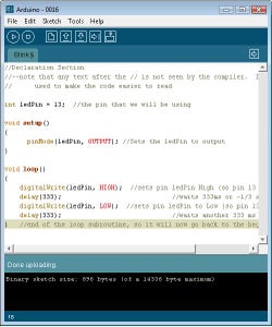
//Declaration Section
//--note that any text after the // is not seen by the compiler. It is only
// used to make the code easier to read
int ledPin = 13; //the pin that we will be using
void setup()
{
pinMode(ledPin, OUTPUT); //Sets the ledPin to output
}
void loop()
{
digitalWrite(ledPin, HIGH); //sets pin ledPin High (so pin 13 is set to 1)
delay(333); //waits 333ms or ~1/3 sec
digitalWrite(ledPin, LOW); //sets pin ledPin to Low (so pin 13 is now equal to 0)
delay(333); //waits another 333 ms
} //end of the loop subroutine, so it will now go back to the beginning
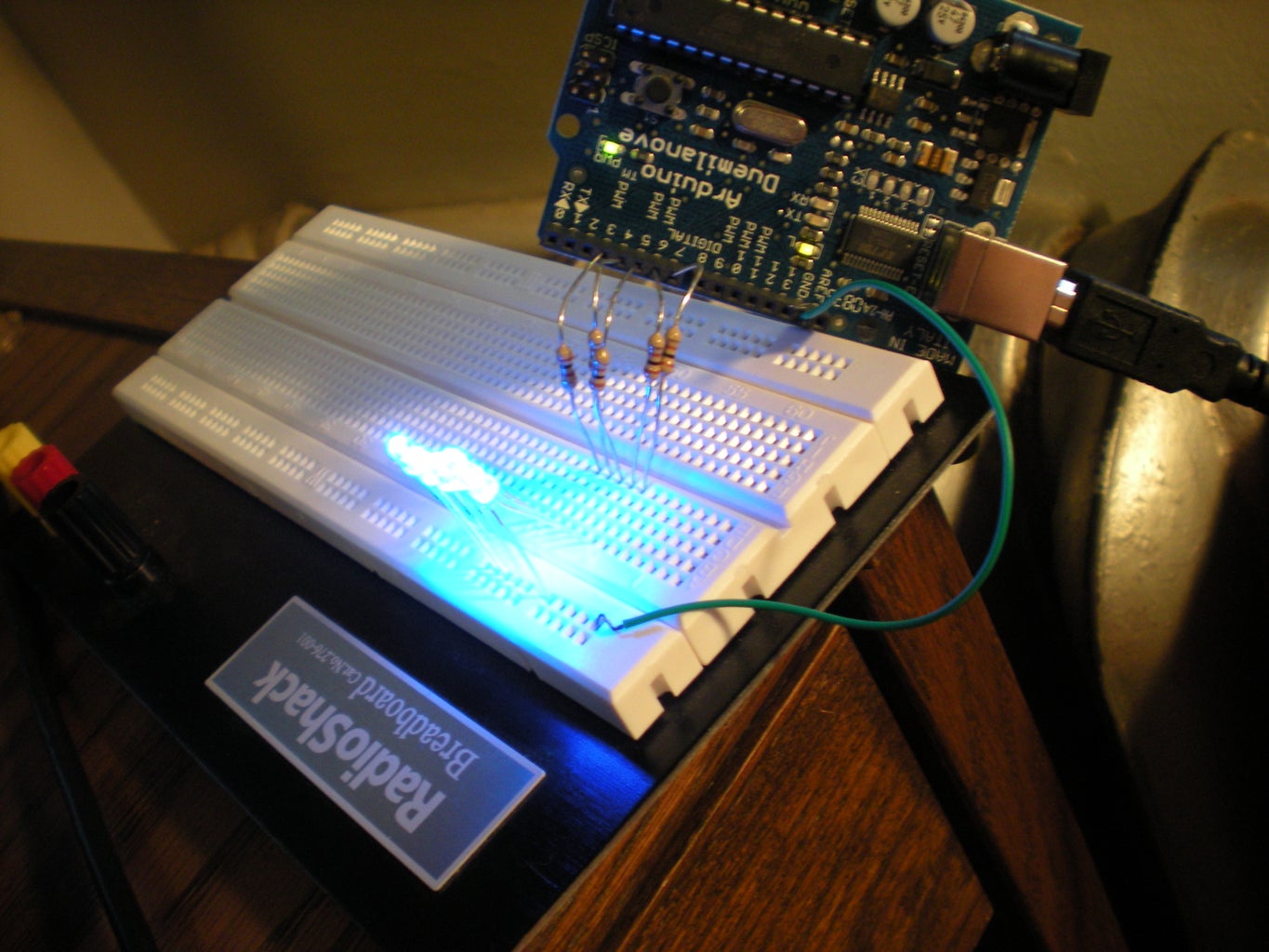
Step 4: Setting Up for Some Port Fun
Now you actually get to attach stuff to your Arduino!!!!!
These instructions use a breadboard, but it should be possible if you have good wire twisting skills to not use one
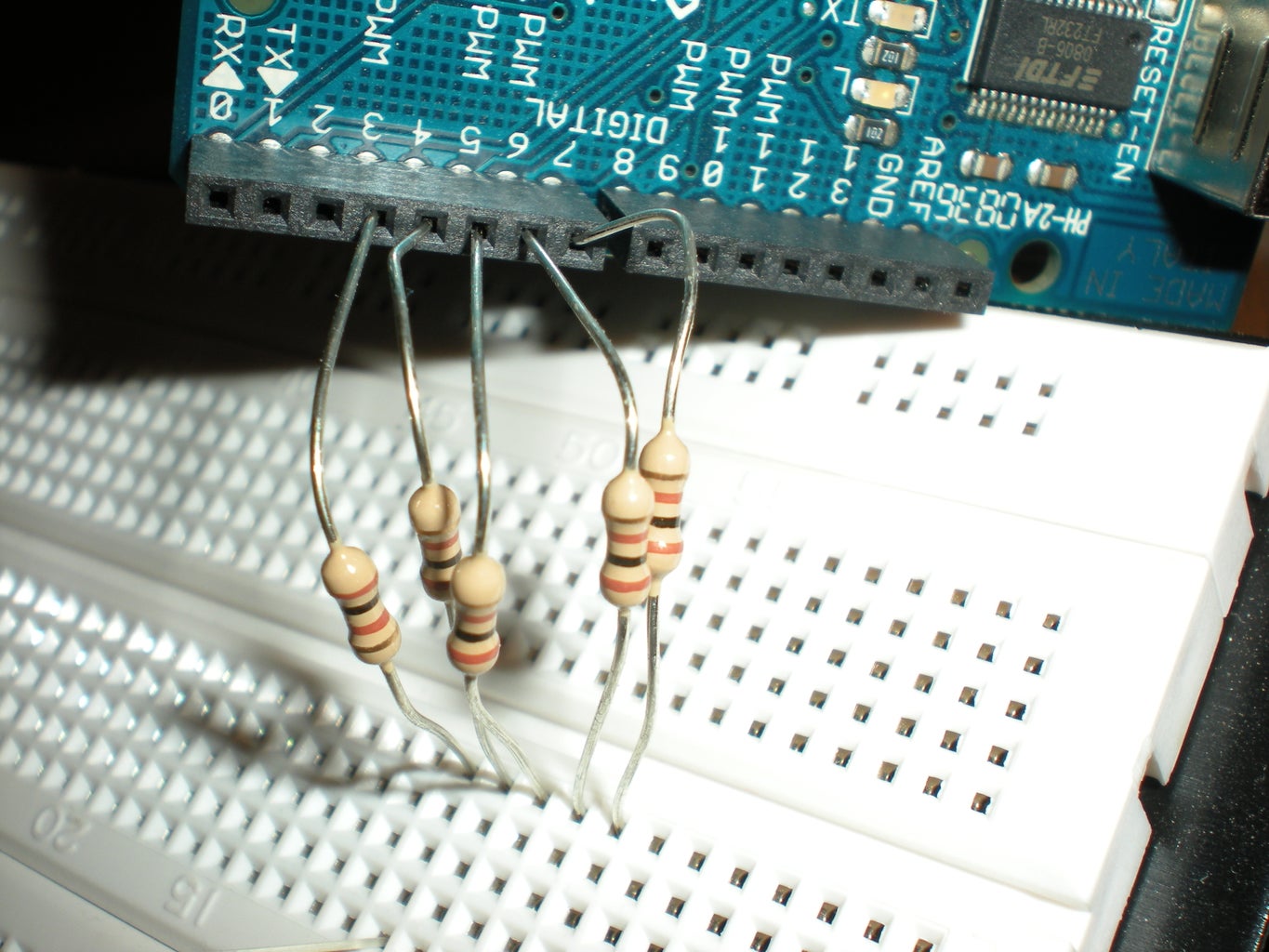
Step 1: Place resistors into pins 3-7 of the Arduino
Step 2: Place the other end of the resistors into the bread board in adjacent rows
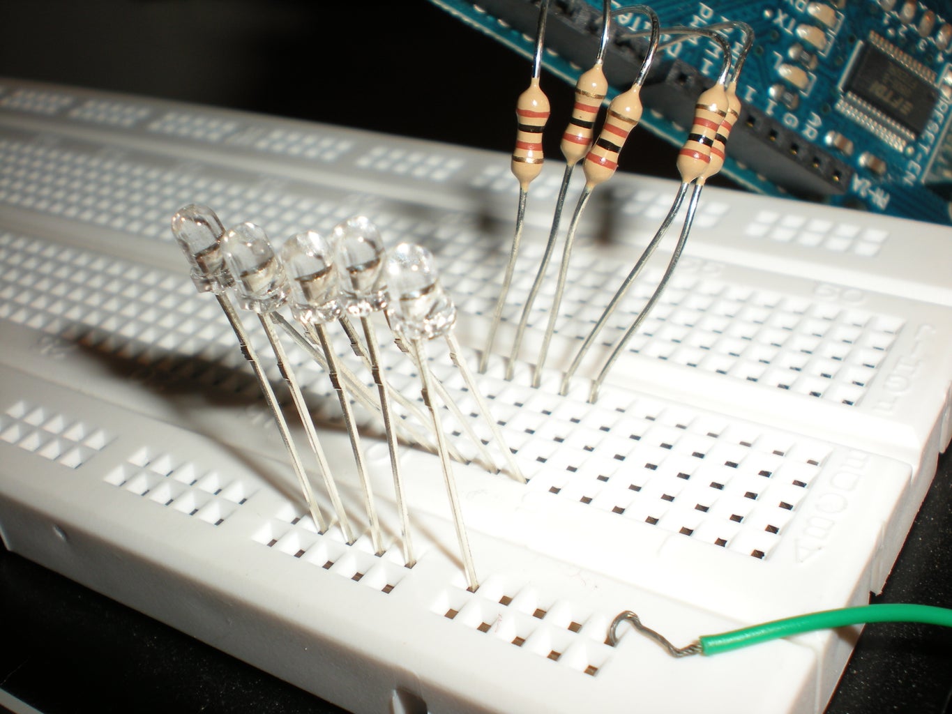
Step 3: Place the long pin of the LEDs into the same row as the resistor (1 LED per resistor)
Step 4: Place the other pin of the LEDs into one of the rails on the side
Step 5: Attach a wire from GND to the rail
Step 5: Programming Ports
Ports are groups of pins. In the arduino, pins 0-7 are controlled by port D and pins 8-13 are controlled by port B.
Advantages of using ports: Faster than going per pin, takes up less code for a smaller program
Disadvantages: Harder to use and debug
I arbitrarily chose port D as my port.
Some basic things to keep in mind for using ports
Variables (X should be replaced by the correct port letter)
DDRX -- Data Direction Register -determines which way data should flow for each pin on the port (0 is input, 1 is output)
PORTX--Data register --holds what data is being output/input to the pins
PINX --Input pins register
The pins in the register are arranged from lower number = Least Significant Bit to Highest number - Most Significant Bit (so to get pins 0-3 to equal 0 and 4-7 to equal 1 it would be PORTD = B11110000)
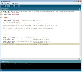
Example Code
int delayTime = 333; //It's better coding style to not have any hard-coded constants like in the previous example
byte portD_HIGH = B11111000;
byte portD_LOW = B00000000;
void setup()
{
DDRD = DDRD | B11111100; //Sets up the pins for output
//a look at what we just did
//the | symbol is used as bitwise OR (if either bit is 1, result will be 1)
//this goes through the register, ORing each bit with the binary to the right of the |
//the B makes the compiler read the 11111100 as binary
//So in summary it sets pins 2-7 to Output and leaves 1 and 2 (which sometimes
//have special functions) alone
}
void loop()
{
PORTD = portD_HIGH; //sets pin ledPin High (so pin 13 is set to 1)
delay(delayTime); //waits 333ms or ~1/3 sec
PORTD = portD_LOW; //sets pin ledPin to Low (so pin 13 is now equal to 0)
delay(delayTime); //waits another 333 ms
} //end of the loop subroutine, so it will now go back to the beginning
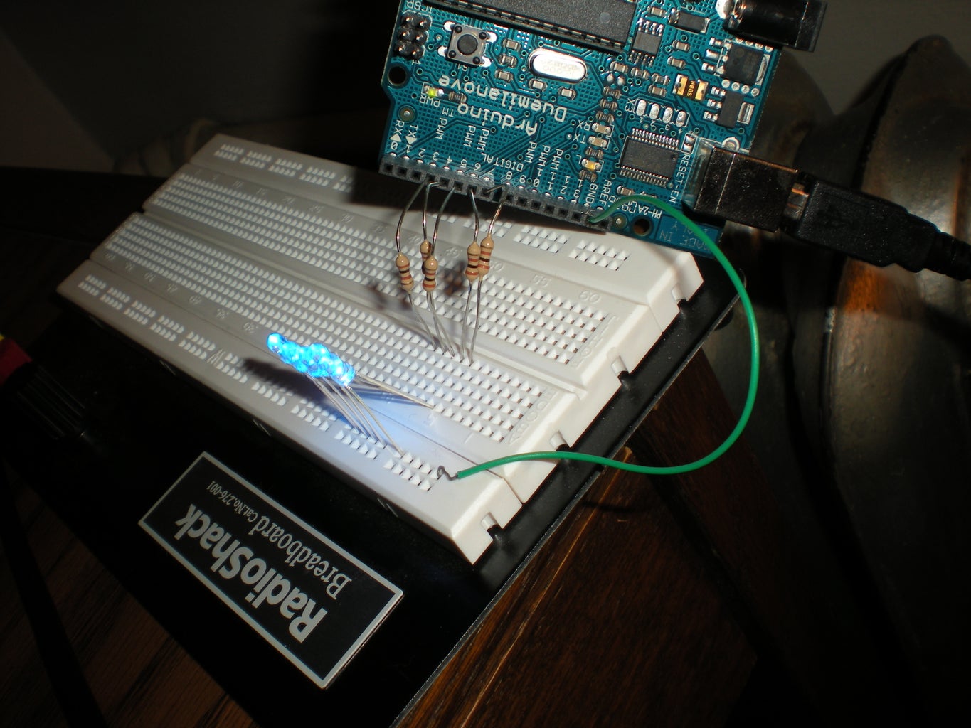
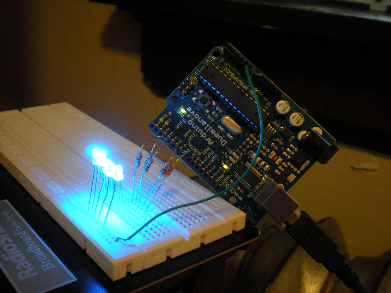
All 5 LEDs should now be blinking merrily away.
Step 6: Fun With Pulsing
So blinky lights are pretty cool, but how about one that Pulses?
The new code we will need to use here is a for loop
the syntax for a for loop is
for(int
}
i.e.
for(int i = 0; i < 9; i++){
}
will set i to 0, go through the loop, then do i++, which makes i equal 1... until i equals 9. When this happens, it will jump to the code after the closing bracket (so the code in the for loop will not be executed with i equal to 9)
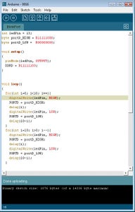
Here's the code, with no comments so you get to figure out what's going on...:
int ledPin = 13;
byte portD_HIGH = B11111000;
byte portD_LOW = B00000000;
void setup()
{
pinMode(ledPin, OUTPUT);
DDRD = B11111100;
}
void loop()
{
for(int i=0; i<10; i++){
digitalWrite(ledPin, HIGH);
PORTD = portD_HIGH;
delay(i);
digitalWrite(ledPin, LOW);
PORTD = portD_LOW;
delay(10-i);
}
for(int i=10; i>0; i--){
digitalWrite(ledPin, HIGH);
PORTD = portD_HIGH;
delay(i);
digitalWrite(ledPin, LOW);
PORTD = portD_LOW;
delay(10-i);
}
}


