

Introduction: Bluetooth PS2 Controller


The original PlayStation 2 controller is still a solid and well-built controller by today's standards. Better yet, they can be had nowadays for a fraction of the cost of a controller with the same quality.
Today we're bringing this 15-year-old controller back from the dead and turning it into a Bluetooth controller by building it a Bluetooth adapter!
Step 1: Watch the Video!
Check out this quick video for a demonstration of the adapter and run-through of all the steps below from start to finish.
Step 2: What We'll Need


We'll be using an Arduino Nano to receive PS2 controller signals from a PS2 controller port.
These signals then get translated to Bluetooth HID signals, which are then sent to our Bluetooth HID module.
The Bluetooth module I'll be using is an HC-05 with RN-42 HID firmware (see my other Instructable on how to flash an HID firmware onto the HC-05).
Other HID modules like the RN-42 HID, BlueSMiRF HID, or BlueFruit EZKey can be used as well.
We'll also be adding an NFC tag inside the adapter to enable "tap to pair" with an NFC enabled mobile device.
Here's a full list of the parts we need:
- Arduino Nano
- HC05 (with HID firmware), or alternate Bluetooth HID module
- USB port (to receive power from the Power Cube), or alternate external power source
- PS2 controller port (see where I salvaged mine below)
- LED
- Resistors: 1k, 10k, 100k, 200k ohms
- NFC writeable tag
- Case to fit all the components
Where to buy
- HC-05: http://amzn.to/2dHlORJ
- Arduino Nano: http://amzn.to/2dHmB57
- Female USB jack: http://amzn.to/2dPQWu6
- NFC Tags: http://amzn.to/2cQGEIe
- PS2 controller: http://amzn.to/2dc8ks2
- Resistor pack: http://amzn.to/2dq71ID
Soldering gear:
- Weller WES51 Analog Soldering Station: http://amzn.to/2dq7Q4m
- MG Chemicals Silver Solder: http://amzn.to/2dHj0nq
- Helping hand: http://amzn.to/2dc553O
Testing gear:
- Multimeter: http://amzn.to/2dc54N6
- Breadboard & Jumpers: http://amzn.to/2dHknm2
Step 3: Salvage Parts


I always try to salvage components from defunct devices. Here is an old PlayStation (PSX) to USB adapter that no longer has driver support for current operating systems. We'll gut the internals of the adapter, but save one of the controller ports, an LED, and the outer casing.
Step 4: Prepare the Bluetooth Module


This HC05 Bluetooth module we're using does not include a break out board. We'll have to solder a few pieces of loose wires to the following pins: TX, RX, VDD, GND, PIO7, and PIO5 (see diagram). Tape up the wires with electrical tape for support.
Step 5: Configure the Bluetooth Module


We'll need to configure the Bluetooth module as an HID gamepad using the Arduino Nano. For RN42 firmware based HID Bluetooth modules, here are the steps to take (refer to manufacturer's manual for any other firmware):
Download and upload the following program to the Arduino:
https://github.com/evankale/RN42Config
This program establishes a software serial communication channel on digital pins D2 and D3 using a baud rate of 9600.
After the program has been uploaded, follow the schematic diagram to connect the Bluetooth module with the Arduino.
Then plug in the Arduino to the computer and enter the following commands into the serial monitor:
- $$$ (puts the Bluetooth module in command mode; the status LED will blink rapidly in this mode)
- SF,1 (factory settings reset)
- S~,6 (set HID mode)
- SN,<name>(sets the device name to <name>)
- SH,0210 (sets the device type to a gamepad device)
- SU,96 (sets default baud rate to 9600)
- R,1 (reboot the Bluetooth module)
Step 6: Upload the Arduino Code
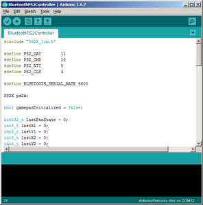
After we have the Bluetooth module configured, we can overwrite the Arduino's program with a program that will take the PS2 controller signals from the controller port, convert them to Bluetooth signals, and send them to the Bluetooth chip.
Plug in the Arduino by itself, then download the following program and upload it to the Arduino:
Step 7: Wire Up the Components
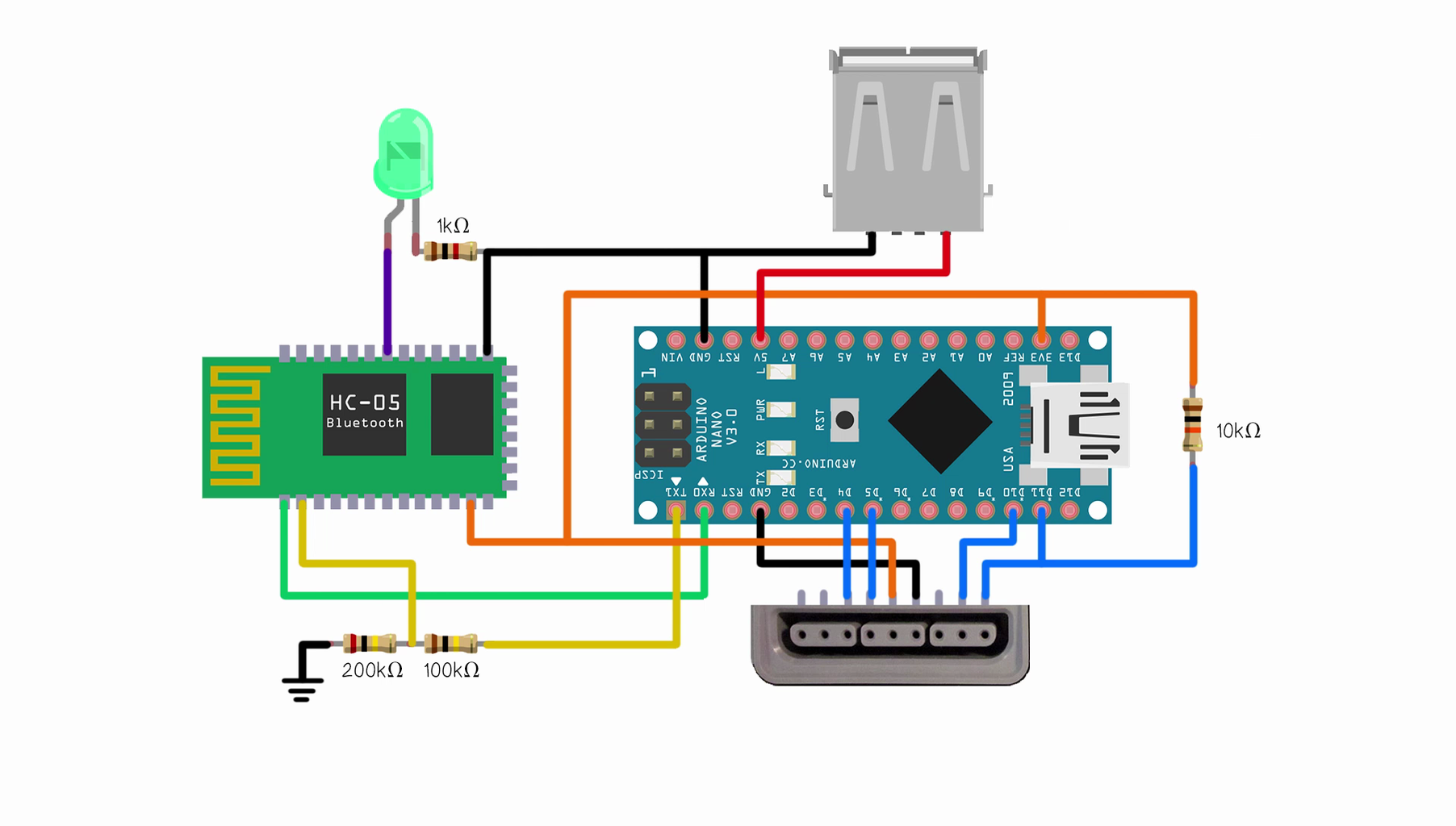


Follow the schematic diagram to connect the PS2 controller port, Bluetooth module, and USB power port to the Arduino.
Plug in a PS2 controller and pair with a Bluetooth enabled device to give it a test. Use a Bluetooth controller testing app (like the Game Controller Test app for Android) to check that all buttons and both analog sticks function properly.
Step 8: Fit the Components Into Case


After having verified the controller to work as intended, we'll need to fit all the components inside the housing.
My case originally had two slots for two controller ports of which I'm now only using one. So I cut out a piece of plastic card to fill the cavity of the unused slot and exposed the USB power port through it.
Use hot glue to hold all the components in place.
Tape the NFC tag onto the back panel of the casing, then close up the case.
Step 9: Write to the NFC Tag


To enable tap-to-pair, we'll have to write a pair command to the NFC tag.
Power up the module with the Power Cube (or your external power source of choice).
Then using a smartphone, pair with the adapter in the phone's Bluetooth settings.
Using an NFC writer app, like TagWriter by NXP, create a new Bluetooth dataset.
Select our adapter, then swipe the tag to write the dataset.
When that's complete, we will be able to tap to connect and tap again to disconnect with the device.
Step 10: Give It a Test!

That's all! Pair up with any Bluetooth enabled device and enjoy!
---
I'd like to thank Bill Porter and his PlayStation 2 Controller Arduino Library which we made use of to read the controller's inputs in the Arduino code.
His blog post can be found here.
If you liked this Instructable, then perhaps you'll like some of my other projects!
You can check them out over at my YouTube channel.
New projects every Thursday! I'll see you next week!

![Tim's Mechanical Spider Leg [LU9685-20CU]](https://content.instructables.com/FFB/5R4I/LVKZ6G6R/FFB5R4ILVKZ6G6R.png?auto=webp&crop=1.2%3A1&frame=1&width=306)


